
Live Chat!
SVX or Subaru Links
Old Lockers
Photo Post
How-To Documents
Message Archive
SVX Shop Search
|
SVX Network Forums Live Chat! SVX or Subaru Links Old Lockers Photo Post How-To Documents Message Archive SVX Shop Search |
IRC users: |
|
#106
 08-14-2013, 07:31 AM
|
|||
|
|||
|
Re: The beginnings of a Megasquirt how-to guide
The MS2 can't support sequential injection. you'll need this too.
http://www.diyautotune.com/catalog/d...kit-p-386.html 
|
|
#107
08-14-2013, 07:57 AM
|
||||
|
||||
|
Re: The beginnings of a Megasquirt how-to guide
Quote:
There will be plenty of spare wires on the 76 pin plug if you want to get creative, and use the stock wiring for things it wasn't meant for - for example, you could mount the IAT sensor near where the MAF was, and use one of the MAF wires for the IAT signal. Or you can drill another hole out of the case and add your own plug, to keep the stock wiring untouched, and the stock ECU and MS easily swappable. The IACV is a 3-wire PWM. I'm not sure whether the MS2 can handle a 3-wire PWM, but it can handle a 2-wire one. I remember reading that there was a way to make a 3-wire one work as if it was a 2-wire one. I used the GM IAT sensor. Cheap enough. A Suby CTS can be made to work, if you have a spare, but because it's a closed sensor design, it won't respond to air temp changes as fast as the open sensor GM one. Also, the plenum gets pretty hot, you might encounter IAT heat soak issues if you mount it there. Maybe try to insulate it?
__________________
'94 Laguna Blue LSi ~159k.......JDM ultra short-geared 3.900 STi Version 7 6-speed w/ Cobb shortshifter, ECUtune 244,8.1mm/256,9.1mm i/e cams, group N motor mounts, '97 grille, JDM clear corners, Momo JDM Legacy GT steering wheel, apkarian's LED tails, silver STi BBS wheels, PWR radiator, redstuff pads f/r, drilled/slotted rotors, bontragerworks rsb #18, Koni/GC 450f/375r coilovers, Megan Racing adjustable lateral links, KMac c/c plates, Stebro exhaust, ECUtune 1v5, Optima battery in the trunk where it belongs. Turbo project '97 Ebony LSi ~137k #036.......Power mode mod, JDM clear corners, BBS wheels. AUX/pocket mod Now a mod "over there"  ............Photo album ............Photo album
|
|
#108
08-14-2013, 08:12 AM
|
|||
|
|||
|
Re: The beginnings of a Megasquirt how-to guide
The IACV only needs a constant +12v source, so it acts as a 2 wire. I'd imagine that if you can switch which wire is ground via rpm/engine temp you can make our 'three' wire iacv work just dandy.
|
|
#109
08-14-2013, 08:45 AM
|
||||
|
||||
|
Re: The beginnings of a Megasquirt how-to guide
Quote:
A 2-wire IACV has a +12V, and another wire which is grounded at the ECU, to close or open the valve. And it also has a spring, which does the opposite. So the ECU and spring push/pull back and forth against each other to change the amount of air going through the valve. A 3-wire IACV has a +12V, and 2 wires grounded the ECU, that push/pull against one another to change the position of the valve. So you will need to do something with both wires in order to have control over the valve. I think what should be done is what's suggested here: http://www.msextra.com/doc/ms2extra/...ware.htm#Fidle (Scroll to "3 Wired Bosch Valves")
__________________
'94 Laguna Blue LSi ~159k.......JDM ultra short-geared 3.900 STi Version 7 6-speed w/ Cobb shortshifter, ECUtune 244,8.1mm/256,9.1mm i/e cams, group N motor mounts, '97 grille, JDM clear corners, Momo JDM Legacy GT steering wheel, apkarian's LED tails, silver STi BBS wheels, PWR radiator, redstuff pads f/r, drilled/slotted rotors, bontragerworks rsb #18, Koni/GC 450f/375r coilovers, Megan Racing adjustable lateral links, KMac c/c plates, Stebro exhaust, ECUtune 1v5, Optima battery in the trunk where it belongs. Turbo project '97 Ebony LSi ~137k #036.......Power mode mod, JDM clear corners, BBS wheels. AUX/pocket mod Now a mod "over there" ............Photo album
|
|
#110
08-14-2013, 10:23 AM
|
|||
|
|||
|
Re: The beginnings of a Megasquirt how-to guide
ah got yuh. you'd need to make a universal io port act as the second control wire.
|
|
#111
08-14-2013, 07:02 PM
|
|||
|
|||
|
Re: The beginnings of a Megasquirt how-to guide
Quote:
The coils are feed 12V, the Ignitor grounds them when the ECU Dwell signal is sent, the Ignitor looks at the current the coil is flowing till it reaches about 4 amps, it then holds that current till the ECU Dwell times out, to turn the Ignitor off. So your switching transistors need to be able to dissipate the heat, while the Ignitor is holding the current at about 4amps. All the heavy current is handled by the Ignitor. Quote:
it is balanced between two voltages that are varied between 1 and 10V. Idle is 5v each side.Harvey.
__________________
One Arm Bloke. Tell it like it is! 95 Lsi. Bordeaux Pearl, Aust. RHD.149,000Kls Subaru BBS wheels. 97 Liberty GX Auto sedan. 320,000Kls. 04 Liberty 30R Auto Premium. 92.000kls.
|
|
#112
08-14-2013, 07:44 PM
|
|||
|
|||
|
Re: The beginnings of a Megasquirt how-to guide
Odd, why on the ecu pinout it clearly labels one as 'open' the other as 'closed'. As I'd imagine it grounds one side or the other to either open or close the IACV seeings how the center wire of the plug is +12v.
|
|
#113
08-14-2013, 10:19 PM
|
|||
|
|||
|
Re: The beginnings of a Megasquirt how-to guide
Quote:
The ECU has two transistors that are oppositely driven. As one increase its current, the other one reduces its current, so that the armature is always held between the two magnets. Harvey.
__________________
One Arm Bloke. Tell it like it is! 95 Lsi. Bordeaux Pearl, Aust. RHD.149,000Kls Subaru BBS wheels. 97 Liberty GX Auto sedan. 320,000Kls. 04 Liberty 30R Auto Premium. 92.000kls.
|
|
#114
08-14-2013, 11:11 PM
|
||||
|
||||
|
Re: The beginnings of a Megasquirt how-to guide
Quote:
__________________
'94 Laguna Blue LSi ~159k.......JDM ultra short-geared 3.900 STi Version 7 6-speed w/ Cobb shortshifter, ECUtune 244,8.1mm/256,9.1mm i/e cams, group N motor mounts, '97 grille, JDM clear corners, Momo JDM Legacy GT steering wheel, apkarian's LED tails, silver STi BBS wheels, PWR radiator, redstuff pads f/r, drilled/slotted rotors, bontragerworks rsb #18, Koni/GC 450f/375r coilovers, Megan Racing adjustable lateral links, KMac c/c plates, Stebro exhaust, ECUtune 1v5, Optima battery in the trunk where it belongs. Turbo project '97 Ebony LSi ~137k #036.......Power mode mod, JDM clear corners, BBS wheels. AUX/pocket mod Now a mod "over there" ............Photo album
|
|
#115
08-15-2013, 07:17 AM
|
|||
|
|||
|
Re: The beginnings of a Megasquirt how-to guide
Quote:
|
|
#116
08-16-2013, 09:29 PM
|
|||
|
|||
|
Re: The beginnings of a Megasquirt how-to guide
Ok, so I'm pretty set on the Zeal Engineering daughterboard for the following reasons:
1. Dual VR conditioners. They're not as small or quite as good as the BrickEMS VR conditioner, but they'll get the job done. 2. 3 outputs. Instead of building 3 more transistor circuits to run the ignition from logic-level to power-level, you can use the 3 LED's + the 3 outputs from the MSExtra into the zeal board to give you 6 good transistor-controlled ignition outputs!  3. PWM idle control. I don't know if I'll need this or not, but it'd be nice to have. 4. Tach driver. Again, I don't think I'll need it, but it might be nice. Though I still think that even with these extra output channels, I'll still need to build one more for the electric cooling fans. So I may just design/etch my own board, but we'll see about that (I may even try having a board made, found a new board-maker, and through-plated holes are SOOOOO much easier/better looking to solder). If I DO DIY my own, I'll do SMD components based on the same chip as the BrickEMS, as it's newer and better (and simpler). That, and I have yet to play with SMD components, and after my LED tail light project, I'm VERY tired of through-hole components! I'm also looking for a cable that has all the pins populated. I haven't pulled mine apart yet, but as it's a relay board patch cable I HIGHLY doubt they're all populated. I've also ditched the idea of using the relay board, There just aren't enough outputs on it for everything. Furthermore, half of the cable is useless as the entire top half of it is grounded on the relay board itself. Talk about useless. If I get *really* fancy, I might add another connector to the megasquirt box (DB9?) for the spark and fuel outputs. I'm still trying to figure out what I want to do for the wiring harness. The majority of my problem is that I want to half-ass it. I want to both have a MS harness, but have a stock harness so that I can run the stock ECU while I'm still trying to get everything sorted. So, I'm trying to find a 2nd stock engine harness, ignitor connector, etc. Because who doesn't love spending twice as much?! As far as actual progress, I did swap the jumpers on my stock board from "Opto" to "VR" triggers for the tach input and output, and I also added the 12v feed wire for the MSextra chip. So, I mean, that's cool and all. EDIT: After looking over the zeal card again, it appears that the PWM and tach outputs are just more transistor circuits, so maybe I can make them work. Last edited by BRZCory; 08-16-2013 at 09:42 PM.
|
|
#117
08-17-2013, 06:39 AM
|
||||
|
||||
|
Re: The beginnings of a Megasquirt how-to guide
Guys, I am not really following this thread, but I am posting this on behalf of a friend who saw and read it:
"The IACV comprises a voltage sensitive rotary solenoid valve, biased towards a central rest position, at which point the valve is held half open by means of a permanent magnet. A double wound coil provides open closed operation from this rest position. This arrangement provides for two way adjustment, constantly variable towards fully open or shut, depending on which coil winding is energised and the level of voltage applied separately to each winding. The mean half open position, held by a permanent magnet ensures fail safe operation. Three electrical connections are involved. The centre pin on the connector is common to both windings and is energised positive at nominal battery voltage. The remaining two connections provide for open and close operation of the valve aligned with a variable voltage, applied via two separate negative polarised control circuits. A practical test has shown that the valve fully opens or closes from the mean rest position, with 8 volts negative applied to either of the designated terminals. The solenoid resistance measures a nominal nine ohms, each side of the common connection."
__________________
Danny 1994 Silver SVX in hybernation, awaiting for the monsterous awakening (Lebanon)  1967 Mercedes-Benz 250SL Euro Specs, Hard/Softtop, White/Red. Under Complete Restoration  2013 Mercedes-Benz SL350 Euro Specs, White/Red. Mint... Another step into SL Collection. ")
|
|
#118
08-17-2013, 08:06 AM
|
|||
|
|||
|
Re: The beginnings of a Megasquirt how-to guide
Thank you for the info!
Attached is the FSM for the fuel injection, and it shows that for the By-pass air control solenoid valve (Or IACV for normal people) it has an "open" end and a "close" end. Open gets 7 volts, close gets 6. Granted, this doesn't tell us much about *how* it functions, so knowing that it's variable throughout the voltage range helps immensely! I was trying to figure out if it was some sort of pulsed stepper motor or something. Page 71 has the drawing of that circuit, controlled by 1 input and 2 transistors. Vurry interesting. Further edit, the factory setup is this: The valve is always open with no signals (and ignition/main relay on). Both circuits inside the IACV send power from the "power" pin (that's connected to the main relay) to the ECU. The "CLOSE" wire (with the ECU sending no signal) will energize the gate on the transistor on the "OPEN" wire, thus allowing current to flow, and "opening" the IACV. When the ECU energizes the "CLOSE" transistor, energy flows through that, and no longer energizes the "OPEN" transistor, thus closing the valve. 1 ECU control, 2 transistors (powerful enough to control the IACV, V=IR, 8v=I * 9ohms, I = 1.1amps, so a 2022 should be fine, TIP120 would be overkill, but still very fine ), and some creative wiring. I may just breadboard this later today, because it just seems cool, maybe with a 555 timer for PWM control. Also, the "OPEN" wire is shielded, but I'm not sure why. The shield isn't connected to the ECU ground at all, so I'm guessing it's to prevent cross-talk between the 2 wires. Now, to figure out how to attach it to megasquirt. I'll assume PWM control, but I need to do some more research on "Flyback" and see if it can control separate IACV OPEN and IACV CLOSE circuits. (This may be irrelivent now that I know how to do it with one wire) I think that everyone should read through that FSM manual to get a basic idea of how the stock system works. It also provides *some* tables with rough numbers for where the factory engineers thought that the EG33 needed additional fuel and timing (just above zero degrees celcuis the enrichment map changes slope for instance). Lots of good info in there. But I'm sure most of you have seen/read it already. Last edited by BRZCory; 08-17-2013 at 08:39 AM.
|
|
#119
08-17-2013, 11:30 AM
|
|||
|
|||
|
Re: The beginnings of a Megasquirt how-to guide
Quote:
Why not buy the diy bob and make your ecu 100% plug and play so you can jusst swap them back and forth as you sort **** out and still drive to work?
|
|
#120
08-17-2013, 11:33 AM
|
|||
|
|||
|
Re: The beginnings of a Megasquirt how-to guide
Put it all on a breadboard!
 What I found was that the "closed" wire stays powered all the time, and the "open" wire is shielded because it's the only one getting a pulsed signal. I'm still at a loss as to why they'd need 2 transistors for this, as it would make more sense to simply eliminate the "closed" side of the circuit, and leave it always grounded, then just modify the "open" signal to suit. Any EE's out there want to fill me in? Maybe a current-limiting resistor between the "CLOSED" collector and the "OPEN" gate would turn the "CLOSED" line off when the open line was energized? First video w/ an 80 ohm resistor between the "CLOSED" collector and "OPEN" gate: 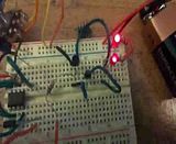 EDIT: Yea, that's what it is. Added a 10kohm resistor between the "CLOSED" collector and the "OPEN" gate, and it effectively creates a switchback circuit, whereby one is on when the other is (mostly) off. I'll upload the vid in a few. Video with a 10k ohm resistor: 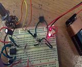 EDIT: It's a variation on a Schmitt Trigger. Yes, I'm an EE newb. Last edited by BRZCory; 08-17-2013 at 12:02 PM.
|
 |
|
|


 Linear Mode

