
Live Chat!
SVX or Subaru Links
Old Lockers
Photo Post
How-To Documents
Message Archive
SVX Shop Search
|
SVX Network Forums Live Chat! SVX or Subaru Links Old Lockers Photo Post How-To Documents Message Archive SVX Shop Search |
IRC users: |
|
#136
 08-20-2013, 11:17 AM
|
||||
|
||||
|
Re: The beginnings of a Megasquirt how-to guide
Quote:
Idea: Maybe using some kind of math trick where you calculate the airflow using the MAP/RPM method, and again using the MAF method, and the discrepancy could give you the air temp? But I don't think any of us have the know-how to make any use of that idea. And if the MAF is going to be connected anyway, then there's not much point, you could just use the MAF itself. The GM IAT sensors are cheap enough that that seems the easier/simpler way to go in any case. Like I said before, also, you can just use a suby CTS if you have a spare, since the resistance/temp curve is known (posted on first page). But it won't respond to temp changes as quickly as an open sensor like the suggested GM one. Depending on where you put it in the intake path and how big of temp fluctuations you expect to see, if may work just fine.
__________________
'94 Laguna Blue LSi ~159k.......JDM ultra short-geared 3.900 STi Version 7 6-speed w/ Cobb shortshifter, ECUtune 244,8.1mm/256,9.1mm i/e cams, group N motor mounts, '97 grille, JDM clear corners, Momo JDM Legacy GT steering wheel, apkarian's LED tails, silver STi BBS wheels, PWR radiator, redstuff pads f/r, drilled/slotted rotors, bontragerworks rsb #18, Koni/GC 450f/375r coilovers, Megan Racing adjustable lateral links, KMac c/c plates, Stebro exhaust, ECUtune 1v5, Optima battery in the trunk where it belongs. Turbo project '97 Ebony LSi ~137k #036.......Power mode mod, JDM clear corners, BBS wheels. AUX/pocket mod Now a mod "over there"  ............Photo album ............Photo album
Last edited by icingdeath88; 08-20-2013 at 11:22 AM. 
|
|
#137
08-20-2013, 12:24 PM
|
|||
|
|||
|
Re: The beginnings of a Megasquirt how-to guide
Hrm. Wonder what that second sensor is hanging off the maf probe then. ohwell.
|
|
#138
08-20-2013, 05:12 PM
|
|||
|
|||
|
Re: The beginnings of a Megasquirt how-to guide
As Cory says, the hot wire is cooled by the air flow and the temp of the air. So the result is a combination of the two, no seperate Air Temp Sensor.
Harvey.
__________________
One Arm Bloke. Tell it like it is! 95 Lsi. Bordeaux Pearl, Aust. RHD.149,000Kls Subaru BBS wheels. 97 Liberty GX Auto sedan. 320,000Kls. 04 Liberty 30R Auto Premium. 92.000kls.
|
|
#139
08-24-2013, 01:43 PM
|
|||
|
|||
|
Re: The beginnings of a Megasquirt how-to guide
4 days with no bumps??!!!!
Well fine then! Here's some IACV testing. I love having a spare motor  (click for video) (click for video)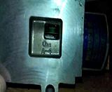 So it's supposed to run at 6 or 7 volts, and the resistance per side is 9 ohms. So that's about .777 amps. 2222's are rated at 1 amp, so they should be sufficent. I guess my next plan is to hook it up to the megasquirt and see what happens. In other news, has anyone else got iacv settings for the EG33? I know you guys have gotten cars to run on the megasquirt, but it seems like I'm doing a lot of work on this IACV and I'm not sure any of it is useful at all... My other question is about basic firing order. I know it's 162435 or something strange like that, but my question is this: Are there 2 cylinders firing at the same time? Or is it strictly one? Because if there are 2 firing at the same time, then I wouldn't feel bad about setting it up as a wasted spark setup. However if it's only 1 at a time, I'm worried for the ignitor. The MS2/extra has enough outputs to do all 6, but then I'd lose outputs to do other things (because I need outputs for the cooling fans, IRIS sytem, and whatever else). Last edited by BRZCory; 08-24-2013 at 01:58 PM.
|
|
#140
08-24-2013, 08:25 PM
|
|||
|
|||
|
Re: The beginnings of a Megasquirt how-to guide
Quote:
Quote:
It would be better to drive the valve from a Digital to Analogy output, if you have one spare, or fit a D to A chip to do it. It really begs the question why use the controller to run the valve at all. If you and not going to operate the valve the same as the ECU does to control the idle speed, why note just drive the transistor array with a variable resistor, and set the idle with a knob, you would still have the Axillary Air Valve to set the cold start idle, and you can just set the idle speed yourself. Quote:
Harvey.
__________________
One Arm Bloke. Tell it like it is! 95 Lsi. Bordeaux Pearl, Aust. RHD.149,000Kls Subaru BBS wheels. 97 Liberty GX Auto sedan. 320,000Kls. 04 Liberty 30R Auto Premium. 92.000kls.
|
|
#141
08-29-2013, 11:13 AM
|
|||
|
|||
|
Re: The beginnings of a Megasquirt how-to guide
See I am going to use the megasquirt to control the idle speed. I only assembled the circuit to see if the wiring diagrams were correct for the IACV. From my testing, it would appear that the 2-transistor circuit detailed in the stock diagram is inaccurate.
The whole reason for this is that megasquirt, as far as I can tell, doesn't support our IACV. It only supports an on/off signal (so, like a high-idle), a stepper motor style, or a PWM signal. If I can get the PWM signal to work, then great. However it's trying to control both an open and close circuits, with just one output. Honestly though, I haven't even looked at it all this week. BackWoodsBob died last Saturday (motorcycle accident) and the funeral is tomorrow, so I've been a bit sidetracked. I'll get back on the megasquirt studying next tuesday or so. Last edited by BRZCory; 08-29-2013 at 11:16 AM.
|
|
#142
08-29-2013, 12:03 PM
|
||||
|
||||
|
Re: The beginnings of a Megasquirt how-to guide
Quote:
Ground to Open-> PWM output of MS Power-> +12V supply Ground to Close-> resistor-> ground http://www.msextra.com/doc/ms2extra/...ware.htm#Fidle (Scroll to "3 Wired Bosch Valves") Our IACV works beautifully in 3-wire PWM mode with the MS3X, for me, so I think it should also work for you if you do the above. If you have issues, try switching the open/closed wires, and setting it to inverted (MS PWM output closes it instead of opens it). (I can explain why, but I'd rather cross that bridge when we come to it. Has to do with the valve potentially closing too much.) Whether it's technically a varying voltage like Harvey explained, or PWM, it should still be controllable as if it were a PWM valve. Think about it, 12V, 50% duty cycle to both the "close" and "open" pins should have the same result as 6V constant on both pins, right? Or, if not exactly the same, then at least similar enough that it should get the job done. Harvey, correct me if I'm way off base, but that's my understanding.
__________________
'94 Laguna Blue LSi ~159k.......JDM ultra short-geared 3.900 STi Version 7 6-speed w/ Cobb shortshifter, ECUtune 244,8.1mm/256,9.1mm i/e cams, group N motor mounts, '97 grille, JDM clear corners, Momo JDM Legacy GT steering wheel, apkarian's LED tails, silver STi BBS wheels, PWR radiator, redstuff pads f/r, drilled/slotted rotors, bontragerworks rsb #18, Koni/GC 450f/375r coilovers, Megan Racing adjustable lateral links, KMac c/c plates, Stebro exhaust, ECUtune 1v5, Optima battery in the trunk where it belongs. Turbo project '97 Ebony LSi ~137k #036.......Power mode mod, JDM clear corners, BBS wheels. AUX/pocket mod Now a mod "over there" ............Photo album
|
|
#143
08-29-2013, 03:50 PM
|
|||
|
|||
|
Re: The beginnings of a Megasquirt how-to guide
Your understanding of PWM is pretty close, but the only thing missing is the time factor. "Duty cycle" = "On time" (Or actually a percentage of on to off).
If your electronics are fast enough, and your frequency slow enough, they'll actually respond to that full 12v, which *could* fry things. (I just made some LED tail lights that DIM via PWM, so I've had a bit of study in this area) That being said, I'm ordering a TIP122 (or a few) now. Along with the mica insulator kits, and a 50w resistor. I also bought the JBPerf V2.1 VR conditioner board, so I'll get to play with that as well. Things I still need: Cable to hook all this up, as most of the DB37 cables I've seen don't have all the pins populated, and I'm going to need most of them Knock sensor control of some sort Wideband Oh, and the rest of my supercharger. But that's another story. Last edited by BRZCory; 08-29-2013 at 04:21 PM.
|
|
#144
08-29-2013, 05:38 PM
|
|||
|
|||
|
Re: The beginnings of a Megasquirt how-to guide
The systems that you both have considered will open and close the valve. The only problem that I see is trying to keep the valve at a steady position.
PWM is an on off signal, full drive, then no drive, like the gearbox solenoids that you can hear vibrate with no oil pressure to damp the vibrations, run at about 50 Hz. Without some external property to do the smoothing, you can only increase the PW frequency to damp the action, but there is a limit to how high a frequency the reluctance of the core in the electromagnets can respond to before they loose movement. The experimenting that you all are doing, will eventually find a way. Harvey.
__________________
One Arm Bloke. Tell it like it is! 95 Lsi. Bordeaux Pearl, Aust. RHD.149,000Kls Subaru BBS wheels. 97 Liberty GX Auto sedan. 320,000Kls. 04 Liberty 30R Auto Premium. 92.000kls.
|
|
#145
09-03-2013, 04:11 PM
|
|||
|
|||
|
Re: The beginnings of a Megasquirt how-to guide
Quote:
I also dug up some more info, lemme see if I can find it. Last edited by BRZCory; 09-03-2013 at 04:36 PM.
|
|
#147
09-08-2013, 03:40 PM
|
|||
|
|||
|
Re: The beginnings of a Megasquirt how-to guide
Ok, progress on the idle controller. Right now I've got this circuit setup on the breadboard, and it seems to work pretty well!
 It does take 2 tip122's, both with heatsinks, and 2x 2+watt 100 ohm resistors, but it works! Megasquirt (well, MSExtra) settings are as follows: PWM, Non-inverted (normal), with a 4x multiplier. Haven't tried it on the car yet, but on the bench, with mah little spare iac, it works!
|
|
#148
09-08-2013, 05:01 PM
|
|||
|
|||
|
Re: The beginnings of a Megasquirt how-to guide
That looks fine mate, what frequency is the PW cycle?
Harvey.
__________________
One Arm Bloke. Tell it like it is! 95 Lsi. Bordeaux Pearl, Aust. RHD.149,000Kls Subaru BBS wheels. 97 Liberty GX Auto sedan. 320,000Kls. 04 Liberty 30R Auto Premium. 92.000kls.
|
|
#149
09-12-2013, 06:04 PM
|
|||
|
|||
|
Re: The beginnings of a Megasquirt how-to guide
Quote:
 The frequency is always 30.5hz with megasquirt. They don't allow you to change that, only the multiplier. So, it'd be 30.5x4 or 122hz. Also, it's only one 2w, 100ohm resistor. In my haste I neglected the fact that when wired internally into the megasquirt, it will be a logic-level input. So, at 5v, it's a 41.6 ohm, 1/2w resistor (just on the PWM input). I'll test it all fully once I get the boards in Next project is a biggie. I've been going back and forth with how I want to wire this whole thing up, but I think I've finally settled on just using the stock ECU connector. So, this weekend, somewhere between the rally-x, the birthday party, the photography session, and mowing the lawn, I'll find time to de-solder the stock ECU connector from my spare ECU. I'd love to make a breakout board for it (or just use the one from DIYBOB) but that's a lot of designing (Or $85) for something that I can just use wires for (and, having three or four spare engine harnesses from other projects, I've got plenty of wires). I'll still need to run a IAT sensor though, so I don't know where I'll add in those wires. The main problem is that I need all those injector outputs, and the stock megasquirt connector just doesn't have enough pins. 6 for the spark, 4 for the cam and crank sensors, etc. The MS3X has plenty of ins and outs, but not mah old box! I also need to actually install the VR2 board. Seems pretty straightforward (after you find the one post on the MS forums that actually describes where your putting everything). So yeah, to-do list: ECU connector VR2 wiring IACV board
|
|
#150
09-15-2013, 07:34 PM
|
|||
|
|||
|
Re: The beginnings of a Megasquirt how-to guide
VR2 board installed (at least the power and outputs are good to go, just the inputs to connector to do yet)
Also scavenged an ECU connector from my spare stock ECU. Now I just need to find/make a case to contain everything. I also apparently need to build logic-level injector driver circuits, and since I need to build 6 of them, I'm probably going to order another custom board for that. We'll see how long my PWM board takes to get here before I decide on a course of action for that.   VR2 install instructions: V+ to 5v on the proto area (for the internal VR2 board, the external ones need 12v) GND to ground Out 1 to Tsel Out 2 to Js10 VR1+ to TachSelect (If you want to use the DB37 pin for that side of the input) VR1- to Spr1 VR2+ to Spr2 VR2- to Spr3 Of course those VR pins are all optional depending on your install, TachSelect goes straight to the DB37 connector, same as the Spr via's. The only thing to watch out for is that *some* of the megasquirt patch cables don't have all of the pins populated with wires. The cable that came with mine (to connect to a relay board) didn't have them populated, which is one of the many reasons I'm using the stock ECU connector. So, buyer beware, read the description.
|
 |
|
|


 Linear Mode

