
Live Chat!
SVX or Subaru Links
Old Lockers
Photo Post
How-To Documents
Message Archive
SVX Shop Search
|
SVX Network Forums Live Chat! SVX or Subaru Links Old Lockers Photo Post How-To Documents Message Archive SVX Shop Search |
IRC users: |
|
#151
 06-02-2008, 11:55 AM
|
||||
|
||||
|
Quote:
Thanks for explaining the AFR curve in the "before" plot!  -Bill
__________________
Retired NASA Rocket Scientist Most famous NASA "Child" - OSIRIS-REx delivered samples from asteroid BENNU to Earth in Sept. 2023 Center Network Member #989 '92 Fully caged, 5 speed, waiting for its fully built EG33 '92 "Test Mule", 4:44 Auto, JDM 4:44 Rear Diff with Mech LSD, Tuned headers, Full one-off suspension '92(?) Laguna, 6 spd and other stuff (still at OT's place) My Locker 
|
|
#152
06-02-2008, 06:18 PM
|
||||
|
||||
|
Quote:
Horse power is a measure of work accomplished. Torque is a measure of a static force. Once torque moves something, HP is developed and can be measured. In the situation being discussed, an increase in torque therefore clearly results in an increase in HP. Therefore the power does not remain the same as you have claimed. However this is a matter of getting ones head around what are rather confusing facts, and does not affect the issue. 
__________________
Trevor, New Zealand. As a child, on cold mornings I gladly stood in cowpats to warm my bare feet, but I detest bull$hit!
|
|
#153
06-02-2008, 06:27 PM
|
|||
|
|||
|
Quote:
When I design something I subscribe to the "KISS" principal, so it is pretty simple.  It uses a LM741 Op-Amp configured as a comparator, comparing a regulated set voltage to the Throttle Position Sensors voltage. When the TP voltage reaches 1.8 V the Op-Amp sets to turn on a transistor to operate a DP/DT relay. One half turns the TCUs Torque Control line off the ECU and on to a regulated 4.5V, that it can pull up and down happily. The other side of the relay inserts a resistor in the A solenoids control line to limit its signal to 5%. This action keeps both the ECU/TCU from posting trouble codes. The Op-Amp has some negative feed back to allow some hysteresis to give a good snap-on, and to prevent a noisy TPS from spurious triggering. The line pressure is normally controlled by the throttle position, more throttle more line pressure, this is the normal way Autos do it. In our box there is another feed to the A solenoid that is used to reduce the line pressure for a number of reasons, cold oil, starter cranking, gear changing. So it can't be turned off all the time.  The circuit looks like this, the Throttle pressure signal is a 12V duty cycle that is run through the dropping resistor to reduce the signal to a 5V signal to mix with the 5V shift signal. The inclusion of the resistor to allow the two signals to drive the solenoid even though they may be opposite. This happens when the throttle is wide open its duty cycle signal is 5%, when the shift is to operate the shift voltage is increased to about 80% to soften the engagement, if the resistor was not used one line would short out the other line, so it acts as an isolator, or voltage divider. When the Small Cars Shift Kit is used, the reduced resistance in the Throttle line causes a higher line pressure that would normally be used, but even with this in place, a full throttle change still has the line pressure reduced through the shift line, so it really does nothing but fool the driver into thinking it is producing a solid change. The other thing that the SCSK can't do, that the Quick Change achieves is that because the Pilot pressure that the A solenoid regulates, is also used to set the pressure behind the shift accumulators, by keeping this pressure from reducing, it reduces any chance of slip due to the longer engagement time, that the softer accumulator gives, so its action is set in line with the throttle pressure as the whole operation is. The Quick Changes action is progressive to the throttle position, no change at all on a light throttle, progressively getting firmer with the throttle position. I'll get a photo up eventually. Harvey.
__________________
One Arm Bloke. Tell it like it is! 95 Lsi. Bordeaux Pearl, Aust. RHD.149,000Kls Subaru BBS wheels. 97 Liberty GX Auto sedan. 320,000Kls. 04 Liberty 30R Auto Premium. 92.000kls.
|
|
#154
06-02-2008, 06:41 PM
|
||||
|
||||
|
Quote:
Like you I am curious and have the exactly same thoughts as you regarding the method involved. However this stumbles because Harvey has mentioned that the torque control is normally used as a safety measure in reverse gear. Surely this is not done away with.  Importantly Harvey has stated that The overall Line pressure is still controlled by the Throttle pressure through the dropping resistor circuit that has to be as normal. This is not correct. The resistor circuit is not involved in the control of solenoid A. The increase in line pressure due to disconnecting the circuit is purely circumstantial. Cheers, Trevor. *<)
__________________
Trevor, New Zealand. As a child, on cold mornings I gladly stood in cowpats to warm my bare feet, but I detest bull$hit!
|
|
#155
06-02-2008, 11:00 PM
|
||||
|
||||
|
Wannarace,
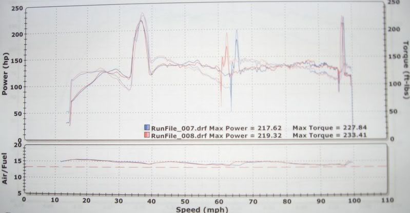
Thanks for posting up the dyno charts. I have been reading this and staying quiet up to now. I have posted the same information in previous threads that you have. See the dyno chart from my SVX:  In this thread-->http://www.subaru-svx.net/forum/show...Akit%2A&page=2 I have explained that I think the spike in lean air/fuel ratios could probably be eliminated if the shifts were super fast. Here is the thread that this info was posted in ---> Thread: http://www.subaru-svx.net/forum/show...ht=Hydrosystem Here's is what I said in this thread: Quote:
I have experienced the same problem that you did with the shifting of the car to 4th gear before I had my valve body modified. If you look at my dyno graph, you'll notice that my car does not shift when yours did after you had your shift kit installed. My power simply kept going then dropped off. It would not shift into 4th gear. Just wanted to let you know that you are not alone. Also wanted to thank you for confirming what I have been stating all along. That I believe you WILL eliminate the air/fuel ratio spike in between shifts with a shift kit. Trust me, your tranny should like it due to the reduced trans temps. If I had another SVX, this'd be one of the first mods no doubt. Send me a PM if you like to discuss further. You may be in an uphill battle trying to convince some people (No offense) that this is worth doing. I never got back on the dyno to prove what I thought it'd do to the air/fuel ratio. Again thanks!  Also, you have proven what I said about he torque/hp jump in between shifts. See my quote above. THANK YOU!!!! I love it!!!! Quote:
__________________
Kevin Thomas 1997 2.2ltr Subaru Impreza Outback Sport Wagon (AWD/Auto) 13.03@100mph 1989 2.7ltr Subaru XT6 (AWD/Auto) 15.912@85.93mph 1996 3.3ltr SVX (AWD/Auto) 15.070@91.38mph ***R.I.P*** 2010 RAV4 AWD Sport (13.717 @ 99.19mph ) 2015 Honda Fit LX CVT (15.2 @ 90mph) Last edited by Myxalplyx; 06-03-2008 at 12:53 PM.
|
|
#156
06-02-2008, 11:25 PM
|
||||
|
||||
|
Quote:
Harvey, I apologize ahead of time for not purchasing your kit when we talked PM (before I had the Level 10 done). I wasn't sure it was doing what Tina charts suggests. As for the bolded area above, I just wanted to confirm the time you suggested from the time I plotted on my dyno chart from a previous post. Quote:
http://www.subaru-svx.net/forum/show...Akit%2A&page=2 I am still wondering why the 2nd to 3rd gear shift is not as powerful as 1st to 2nd and 3rd to 4th. Same 'issue' I have. I still do not like my 2nd-3rd gear shift even though it is still good. The 'neck-snapping' shift is not there or as apparent as the other gear shifts.Harvey, congrats on your work. I want to purchase this kit despite the valve body job I have already. That 1-2 shift is neck snapping. I like a lot and I don't think I quite feel that much torque going through the gears. Good luck and I hope you sell a ton of these. I wish I could apply your kit to my XT6. I'd do it tomorrow.
__________________
Kevin Thomas 1997 2.2ltr Subaru Impreza Outback Sport Wagon (AWD/Auto) 13.03@100mph 1989 2.7ltr Subaru XT6 (AWD/Auto) 15.912@85.93mph 1996 3.3ltr SVX (AWD/Auto) 15.070@91.38mph ***R.I.P*** 2010 RAV4 AWD Sport (13.717 @ 99.19mph ) 2015 Honda Fit LX CVT (15.2 @ 90mph) Last edited by Myxalplyx; 06-03-2008 at 05:46 PM.
|
|
#157
06-03-2008, 05:48 PM
|
|||
|
|||
|
Quote:
The differences in the 1-2 and 2-3 changes is, when the box is in first the forward clutch is on, to go to second the brake band only has to be applied, the forward clutch is still used. If the band slips a bit or it is late to apply, the box is still in first so you won't notice it, you just get a later change. The 2-3 change is different. The band has to be released, and the high clutch has to be applied. This takes a bit of timing, both with the valve body and the TCU. If the band is released before the high clutch comes on, it will 'flare', (actually it still has the forward clutch on, so it goes back to first), till the high clutch comes on to go to 3rd. So it doesn't have the snap action of just applying the band, it takes a bit of shuffling to do. Older 3 speed boxs did this change over using the same applied pressure, releasing the band and applying the high clutch with the same applied pressure. Because our 4 speed uses the band again for 4th, it has a much more involved release/apply system. Hence the reason for the difference in the changes. The 3-4 change is a bit like the 1-2, as the high clutch is still on and the band is applied to hold the front sun gear. If the band slips in 4th, it just goes back to 3rd. But only having to apply the band, gives the same snappy change as 1-2. Harvey.
__________________
One Arm Bloke. Tell it like it is! 95 Lsi. Bordeaux Pearl, Aust. RHD.149,000Kls Subaru BBS wheels. 97 Liberty GX Auto sedan. 320,000Kls. 04 Liberty 30R Auto Premium. 92.000kls.
|
|
#158
06-06-2008, 02:04 AM
|
||||
|
||||
|
Refer post #153.
When I design something I subscribe to the "KISS" principal, so it is pretty simple.
It uses a LM741 Op-Amp configured as a comparator, comparing a regulated set voltage to the Throttle Position Sensors voltage. When the TP voltage reaches 1.8 V the Op-Amp sets to turn on a transistor to operate a DP/DT relay. Why not a simple transistor driven voltage sensitive DPDT relay? I gather there is a direct connection to the TPS. This means that whenever the throttle position provides 1.8 V. or more, torque reduction can not occur and line pressure runs free, regardless. One half turns the TCUs Torque Control line off the ECU and on to a regulated 4.5V, that it can pull up and down happily. This indicates that the torque control signal is applied to the output from a 4.5 volt regulated supply. Phil has advised that the torque control is a binary switch not a voltage. It is either On or Off. Therefore the described arrangement will ask the torque control to short circuit a voltage regulated supply, backed up by 14 volts. Interesting stuff. The other side of the relay inserts a resistor in the A solenoids control line to limit its signal to 5%. This action keeps both the ECU/TCU from posting trouble codes. The circuit looks like this, the Throttle pressure signal is a 12V duty cycle that is run through the dropping resistor to reduce the signal to a 5V. signal to mix with the 5V shift signal. It is therefore claimed that the shift signal to the solenoid is at 5v. The inclusion of the resistor to allow the two signals to drive the solenoid even though they may be opposite. Opposite? At negative potential? This happens when the throttle is wide open its duty cycle signal is 5%, when the shift is to operate the shift voltage is increased to about 80% to soften the engagement, if the resistor was not used one line would short out the other line, Why? They are of the same polarity. so it acts as an isolator, or voltage divider. In order to operate as a voltage divider the so called throttle signal must be at negative potential. Everything indicates that the resistor circuit must be at negative potential, which it is not. When the Small Cars Shift Kit is used, the reduced resistance in the Throttle line causes a higher line pressure that (?than) would normally be used, but even with this in place, a full throttle change still has the line pressure reduced through the shift line, Exactly how? so it really does nothing but fool the driver into thinking it is producing a solid change. (Not according to those who have it. The secondary resistor included in the kit is of high resistance and is included only to prevent a fault signal. The effect equates with fully opening the circuit, which has been found to have a definite effect, confirmed by many who have tried it.) The "Q C" may work, but not in the way intended or described and only as result of luck.
__________________
Trevor, New Zealand. As a child, on cold mornings I gladly stood in cowpats to warm my bare feet, but I detest bull$hit!
|
|
#159
06-06-2008, 02:51 AM
|
||||
|
||||
|
Kiss/rs
At the moment with my brain still loose in my skull, bending down makes things spin, so that I am unable to undertake experimental work myself. I hope that someone will have a crack at the following idea. This does not mean that I entirely agree with the mod. involved, which is carried out entirely at the users choice and risk.
Shift kit, KISS/RS (simple, Rapid Shift) Requirement. On a partial opening of the throttle, insert a resistance in the torque control and line pressure signal circuits connected to the TCU, so as to prevent these from operating, while eliminating any abrupt, complete opening of the circuits as well as fault signals. As a result torque control will be eliminated and line pressure increased to controlled pump output pressure. Features. Cost effective, simple easily understood system, easily installed by the user at minimal cost i.e. bugger all for those who have a junk box. Method. Micro switch operated directly from the throttle spindle. Components. Alternative 1. Special bracket & actuator user made, one S.P.D.T. miniature micro switch, one D.P.D.T. 12 volt 10 -15 amp relay, two carbon resistors, insulated hook up wire, connectors, fastenings. Alternative 2. Special bracket & actuator user made, one D.P.D.T. micro switch, two carbon resistors, insulated hook up wire, connectors, fastenings. Component Specifications. (1) Micro Switch with lever actuation, S.P.D.T. Size and switching capacity not important. Maximum over travel, which largely depends on maximum lever length and this can be extended. (The existing lever can easily be lengthened by sweat soldering an extension, and a brass/bronze lever is therefore preferable. Otherwise the extension can be epoxy glued.) Relay, 12 Volt operating, say 10 - 15 Amp nominal switching capacity. Otherwise users choice of connecting terminals and mounting etc. Give anything you have in the junk box a try. (2) Micro Switch, D.P.D.T. Maximum switch capacity available within a suitable size. Otherwise as (1) above. An alternative is to mount two switches in tandem. Again check the junk box. (1&2) Actuator, comprising a light metal strip 75 mm/3” long, 1-12 mm/3/8-1/2” wide. (1&2) Bracket. Sheet metal right angle bracket, to rigidly mount the micro switch, using the existing two screws at the outside end of the throttle spindle support. To rise upwards and then outwards to support the switch from underneath, so that the lever moves backwards and forwards. Holes drilled accordingly. Innermost switch mounting holes slotted to allow for adjustment. (1&2) Two carbon film resistors, 180 - 470 ohm, 1 watt, to be each chosen after practical testing Method Of Operation. A strip of steel is epoxy glued to the outside of the quadrant operated by the throttle peddle cable, so the it protrudes above the edge in order to strike the lever of a micro switch. The switch is mounted to the outside of the throttle spindle by means of suitable bracket. The switch lever is aligned close to the outside of the quadrant, clear of the second outer quadrant, so that in the closed throttle position, the switch is activated by the protruding strip at the maximum of available over travel. Therefore the switch lever will be released and the N/C contacts close, after the throttle is past part way opened. The normally closed contacts are utilised to operate a relay (1) or directly close the circuitry (2). As a result resistors connected across the two circuits, which have been intentionally broken, are brought into play. It will be seen that the switch position can be adjusted to set the point of throttle opening, where the circuit will become activated. If a relay is used and a S.P.D.T micro switch as in (1), the normally open relay contacts are connected across the resistors. An ignition switch controlled auxiliary supply is connected to the relay and the other side grounded via a lead to the micro switch N.C. contacts. Exact details can be discussed with anyone wishing to install the system. Suitable micro switches are manufactured by Cherry Corp. as well many others. Relays are a dime a dozen and many could have one or both items in their junk box. P.S. If any member wishes to test and finalise this project, make brackets and source components so at to offer a kit, go for it, you will have my assistance. I have no financial reward in mind and all is for free. Those who have thoughts about me stealing ideas, should refer to post #57.
__________________
Trevor, New Zealand. As a child, on cold mornings I gladly stood in cowpats to warm my bare feet, but I detest bull$hit!
Last edited by Trevor; 06-06-2008 at 04:50 PM. Reason: P.S.
|
|
#160
06-06-2008, 05:11 AM
|
||||
|
||||
|
When you guys start talking like this, the conversation goes to another level. Interesting stuff regardless. I will catch up with understanding by 2020.
__________________
Kevin Thomas 1997 2.2ltr Subaru Impreza Outback Sport Wagon (AWD/Auto) 13.03@100mph 1989 2.7ltr Subaru XT6 (AWD/Auto) 15.912@85.93mph 1996 3.3ltr SVX (AWD/Auto) 15.070@91.38mph ***R.I.P*** 2010 RAV4 AWD Sport (13.717 @ 99.19mph ) 2015 Honda Fit LX CVT (15.2 @ 90mph)
|
|
#161
06-06-2008, 10:36 PM
|
|||
|
|||
|
Quote:
You have either not understood, or have not comprehended, any of the explanation that I have written, and I have neither the time, nor the inclination to explain it to you again. Harvey.
__________________
One Arm Bloke. Tell it like it is! 95 Lsi. Bordeaux Pearl, Aust. RHD.149,000Kls Subaru BBS wheels. 97 Liberty GX Auto sedan. 320,000Kls. 04 Liberty 30R Auto Premium. 92.000kls.
|
|
#162
06-06-2008, 11:15 PM
|
|||
|
|||
|
[QUOTE=Trevor;550856]At the moment with my brain still loose in my skull, bending down makes things spin, so that I am unable to undertake experimental work myself. I hope that someone will have a crack at the following idea. This does not mean that I entirely agree with the mod. involved, which is carried out entirely at the users choice and risk.
(1&2) Bracket. Sheet metal right angle bracket, to rigidly mount the micro switch, using the existing two screws at the outside end of the throttle spindle support. To rise upwards and then outwards to support the switch from underneath, so that the lever moves backwards and forwards. Holes drilled accordingly. Innermost switch mounting holes slotted to allow for adjustment. A strip of steel is epoxy glued to the outside of the quadrant operated by the throttle peddle cable, so the it protrudes above the edge in order to strike the lever of a micro switch. The switch is mounted to the outside of the throttle spindle by means of suitable bracket. The switch lever is aligned close to the outside of the quadrant, clear of the second outer quadrant, so that in the closed throttle position, the switch is activated by the protruding strip at the maximum of available over travel. Therefore the switch lever will be released and the N/C contacts close, after the throttle is past part way opened. This would be funny, if it wasn't so stupidly serious.  Here you cobble up a thought, that you will not be testing, and you ask somebody else to try it at their own risk.  You can't be fuggan serious. You can't be fuggan serious. You are telling this lucky sucker to glue some bits to the throttle quadrant on the throttle shaft, and go out and try killing themselves, or somebody else. I am absolutely astounded that you would be so irresponsible as to suggest such a dangeriously modification.  Harvey.
__________________
One Arm Bloke. Tell it like it is! 95 Lsi. Bordeaux Pearl, Aust. RHD.149,000Kls Subaru BBS wheels. 97 Liberty GX Auto sedan. 320,000Kls. 04 Liberty 30R Auto Premium. 92.000kls.
|
|
#163
06-06-2008, 11:20 PM
|
|||
|
|||
|
On a lighter note.
The first delivery of "Quick Change" has arrived in Ohio.
Only took 14 days to get there. Harvey.
__________________
One Arm Bloke. Tell it like it is! 95 Lsi. Bordeaux Pearl, Aust. RHD.149,000Kls Subaru BBS wheels. 97 Liberty GX Auto sedan. 320,000Kls. 04 Liberty 30R Auto Premium. 92.000kls.
|
|
#164
06-07-2008, 12:05 AM
|
||||
|
||||
|
Quote:
__________________
Trevor, New Zealand. As a child, on cold mornings I gladly stood in cowpats to warm my bare feet, but I detest bull$hit!
|
|
#165
06-07-2008, 12:19 AM
|
|||
|
|||
|
Quote:
Quote:
Let's leave it at that.
__________________
Chris SVX World Network Administrator -1993 Subaru SVX LS-L, Barcelona Red, #46, 160,000+ Miles (Sold to SomethingElse )-2011 Toyota Sienna SE, Black, 30,000+ Miles (Swagger Wagon  ) )-2002 BMW R 1150R ABS, Black, 26,000+ Miles (Daily Driver )SVX Owner from February 1997 to March 2008 SVX Online Community Member since February 1998 SVX World Network Member since February 2002, Member #520 Life is a game. Play to win. The world belongs to those who can laugh at it.
|
 |
|
|


 Linear Mode

