
Live Chat!
SVX or Subaru Links
Old Lockers
Photo Post
How-To Documents
Message Archive
SVX Shop Search
|
SVX Network Forums Live Chat! SVX or Subaru Links Old Lockers Photo Post How-To Documents Message Archive SVX Shop Search |
IRC users: |
|
#1
 04-02-2009, 12:03 AM
|
||||
|
||||
|
FRESH START: Alternator Wiring Upgrade Configuration
The original thread got very misleading and confusing and it was probably because I was not very clear. I would like to start over again and be more understandable on what was done and my options. Please bear with me on this.
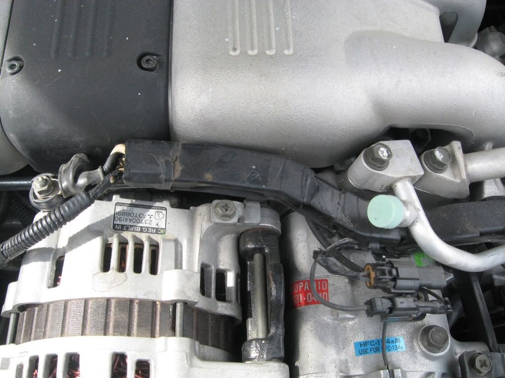
Trevor, Thank you so much for all of the time you have invested in this on my behalf. It is most appreciated. As you said, the wiring diagram is most confusing when compared with what is actually in place. What I see in person is not actually what is in the schematics. Let's start over. HISTORY Like most members, I had original factory circuitry that was never modified in any way. At one point, the only change that was made was the addition of a 4 gauge wire between the battery and the alternator, the now-famous “alternator wiring upgrade”. That was done on my 1996 Polo back in 2002. I had previously done the same mod on my 1992 pearlie. Earlier this year I noticed that the ends of the two white wires that ran through the black plastic conduit among the top of the engine, TO the alternator, had cracks in the insulation and had become brittle. They were the two white wires that attached directly to the alternator charging post. At the same time, I also noticed that the two wires attached the alternator plug on the side of the alternator were dried out and brittle as well. These two wires ran FROM the alternator back through the same black plastic conduit. Both of these had deteriorated, probably due to age and heat from the engine compartment. I bought a new alternator plug with the two wires already attached. Before replacing the alternator plug with the new one, I decided to open the black plastic conduit to see what the wires looked like inside. The two small wires that were attached to the original alternator plug looked fine. I thought I would just install a new alternator plug, soldering the wires on the new plug to the same wires that were connected to the old one. No problem. The two white wires that were connected to the alternator charging post with ring terminals were dried out and cracked their entire length. I thought I would follow them back until I found good wire, trim them and solder replacement wires to them and run them back to their original connection at the alternator charging post. So all I would have done is remove bad wire, replace it with good wire and keep the original connections, with all the wires running through the plastic conduit, as originally designed But the black plastic channel was breaking apart and very brittle. At first I thought about running all of those wires through split loom for protection, as had done before on my 92 pearlie, but the loom would last only about 2 months before it needed replacimng because of engine vheat deforming it. See photo below of the 92, with the looms now replacing the plastic conduit. I attempted using the split loom again on my 96 a few years ago (before I found a used black plastic conduit) This was more heat-resistant, but still lasted only about 4-6 months before it needed replacing. Here is a photo of the split loom, with original black plastic conduit in place, taken about a year ago. The conduit has deteriorated since then. I decided not to use either the split-wire loom or the black conduit, so I routed the wires a little differently. The two wires FROM the new alternator plug (in the side of the alternator) were only lengthened about 10" so that they would run behind the alternator and under the engine manifold, instead of along the top of the engine as originally done. They still are connected in the same way as the original wires were, just a little longer. It was the two white wires from the charging post that is causing all of the concern here. I mistakenly thought that long as I was trimming the bad wires back so far to solder in good wire, I could just attach them directly to the battery instead of running them back to the alternator. Because the heavy 4 gauge power wire of the alternator wiring upgrade gave me the same 13V at the battery as the alternator, I assumed it would not make a difference-- different connection point, same voltage. I did not think I was bypassing a fusible link in the original circuit. The rest is history. So here is what we currently have: ALTERNATOR PLUG: No difference or changes at all. New plug replacing old plug, with their wires lengthened to allow them to run under the manifold instead of on top. THE TWO WHITE WIRES: They were cut back to where there was good wire, new ring terminals attached and connected directly to the battery instead of the alternator charging post. This seems to also bypass the safety fusible link circuit. These are the only wires that need attention OPTIONS: A. Remove the two white wires now attached to the battery, lengthen them enough to reach their original connection point at the alternator post. That’s it. Original circuitry as designed is maintained. Fusible link in circuit is active. The only difference is that the wires are new and not degraded. B. Remove the two white wires now attached to the battery, and splice then together to form one larger gauge wire. Attach a fusible link between the end of that wire and the battery. Fusible link protection is maintained. [/B] OR C. Remove the two white wires from the battery. Do not splice them together, but attach a fusible link to each wire and connect both of them back to the battery. Fusible link protection is still maintained. 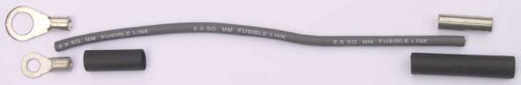  More information on this can be found on THIS WEBSITE I think B or C above would be the most desirable options for keeping an uncluttered look while providing overload protection for the 10 gauge wire circuits. Option A requires nothing to be determined. We are just returning to the stock configuration, only replacing damaged wires with new ones Options B and C require either the amperage rating or the size of the fusible link to be determined. Available fusible links range from 30A to 100A. Fusible link wire is determined by the size of the original wires it is protecting, always being 4 numbers smaller than the wire it is connected to. The 2 white wires we are protecting are 10 gauge, so the proper fusible link wire use would be smaller 14 gauge, or FL-14. This is a gray color, same as the fusible link in our underhood fuse box. Fusible link ratings (wire size) are coded by color. Any final suggestions? This will be my final posting on this topic and I thank everyone here for their concerns and valuable input. .
__________________
. Subaru Ambassador 1996 Polo Green LSi #216..138,100 miles...SOLD JFICX8659TH100216.....Date of Manufacture: November 16, 1995..... Fuji Heavy Industries..Ōta North Plant....Ōta City,. Gunma Prefecture, Japan In-Service Date: January 2, 1997 "The Pristine Green Polo Machine First Polo Green on the Network First Clear front turn signals, JDM Alcyone hood emblem, rear panel, and BOXER engine cover on the Network (US) (2000) First 5000K HID factory fog lights (2007) First SVX JDM BBS wheels on a USDM SVX (2013) HID lighting (5000K) for headlight and H3 fog lights, PIAA SuperExtreme 120W high beams, rebuilt EG33 longblock, Cometic head gaskets, Phase II flexplate, AMR aluminum radiator with custom silicone hoses, 160A high-output alternator in aluminum-ceramic coated case, new design alternator wiring upgrade v.4, rare factory headlight protectors, refinished JDM BBS mesh aluminum wheels and custom, polished billet aluminum new hex center caps, LED grille mod, R1 Concepts high-carbon cryo slotted rotors, Akebono ceramic pads, Goodridge S/S braided brake lines, Smallcar Stage 1 shift kit, ThermalTech aluminum/ceramic-coated valve covers, Energy Suspension urethane front & rear swaybar bushings, Bontrager22 rear swaybar with QS Components Chromoly Teflon/Kevlar endlinks, "$15.00/5 minute" suspension mod. Hella Supertone horns, Custom stainless steel exhaust system with 2" headpipes, Magnaflow cats, AeroTurbine AR25 resonator /AWD "Bullet" muffler. R.I.P. 2010 Subaru Outback Limited 2.5 CVT...338,000 miles. Totaled by a 1,300 lb. COW March 4, 2016  2014 Hyundai Avante Limited ...178,000 miles. Actually quieter and smoother than the Outback  2007 Mazda Miata MX-5 PRHT...102,000 miles. Plenty of parts, service and windshields.  4th Registered Network member 2/21/2001 My NEW locker..I...My Email..I..Wikipedia/SVX . . Last edited by svxcess; 12-04-2018 at 08:59 PM. 
|
|
#2
04-02-2009, 03:51 AM
|
||||
|
||||
|
Re: FRESH START: Alternator Wiring Upgrade Configuration
Good idea to start afresh. You confirm your intelligence as I would expect. You also confirm that you have a very real reason to become confused.
My JDM car does not have the two white wires which you describe, connected to the alternator charging post by means of ring terminals. You advise that they ran along the top of engine but not where they were finally terminated, i.e. were connected to at their opposite ends. It is these wires which have caused the confusion, particularly as they are white. They would provide battery volts so that I wonder if a previous owner fitted them, to supply an accessory of some sort. So as not to restore confusion, please at present keep these two white rogue wires as the sole topic . Poosibly there is another SVX available, that you could compare with yours, as a means of ensuring the rogue wires are original and connected accordingly? This has been a long haul but we will stick with it, there being no drastic problem other than confused wiring.  Sincerely, Trevor.
__________________
Trevor, New Zealand. As a child, on cold mornings I gladly stood in cowpats to warm my bare feet, but I detest bull$hit! 
|
|
#3
04-02-2009, 07:56 AM
|
||||
|
||||
|
Re: FRESH START: Alternator Wiring Upgrade Configuration
John,
I agree with Trevor on the desire to have more description of the "white wires". Can you take a few more pics and post them up? -Bill
__________________
Retired NASA Rocket Scientist Most famous NASA "Child" - OSIRIS-REx delivered samples from asteroid BENNU to Earth in Sept. 2023 Center Network Member #989 '92 Fully caged, 5 speed, waiting for its fully built EG33 '92 "Test Mule", 4:44 Auto, JDM 4:44 Rear Diff with Mech LSD, Tuned headers, Full one-off suspension '92(?) Laguna, 6 spd and other stuff (still at OT's place) My Locker
|
|
#4
04-02-2009, 08:08 AM
|
|||||
|
|||||
|
Re: FRESH START: Alternator Wiring Upgrade Configuration
Good idea to start afresh. You confirm your intelligence as I would expect. You also confirm that you have a very real reason to become confused.
Quote:
Quote:
If other members here can support my observation, please do. Has anyyone else found there to be 2 white wires attached at the alternator post? Having removed alternators from other SVX's, I have had to remove these 2 wires many times. Is it possible that the JDM cars (Japan, Australia, NZ) have only one wire instead of two? Can owners of these cars verify that? Quote:
Quote:
Quote:
.
__________________
. Subaru Ambassador 1996 Polo Green LSi #216..138,100 miles...SOLD JFICX8659TH100216.....Date of Manufacture: November 16, 1995..... Fuji Heavy Industries..Ōta North Plant....Ōta City,. Gunma Prefecture, Japan In-Service Date: January 2, 1997 "The Pristine Green Polo Machine First Polo Green on the Network First Clear front turn signals, JDM Alcyone hood emblem, rear panel, and BOXER engine cover on the Network (US) (2000) First 5000K HID factory fog lights (2007) First SVX JDM BBS wheels on a USDM SVX (2013) HID lighting (5000K) for headlight and H3 fog lights, PIAA SuperExtreme 120W high beams, rebuilt EG33 longblock, Cometic head gaskets, Phase II flexplate, AMR aluminum radiator with custom silicone hoses, 160A high-output alternator in aluminum-ceramic coated case, new design alternator wiring upgrade v.4, rare factory headlight protectors, refinished JDM BBS mesh aluminum wheels and custom, polished billet aluminum new hex center caps, LED grille mod, R1 Concepts high-carbon cryo slotted rotors, Akebono ceramic pads, Goodridge S/S braided brake lines, Smallcar Stage 1 shift kit, ThermalTech aluminum/ceramic-coated valve covers, Energy Suspension urethane front & rear swaybar bushings, Bontrager22 rear swaybar with QS Components Chromoly Teflon/Kevlar endlinks, "$15.00/5 minute" suspension mod. Hella Supertone horns, Custom stainless steel exhaust system with 2" headpipes, Magnaflow cats, AeroTurbine AR25 resonator /AWD "Bullet" muffler. R.I.P. 2010 Subaru Outback Limited 2.5 CVT...338,000 miles. Totaled by a 1,300 lb. COW March 4, 2016 2014 Hyundai Avante Limited ...178,000 miles. Actually quieter and smoother than the Outback 2007 Mazda Miata MX-5 PRHT...102,000 miles. Plenty of parts, service and windshields. 4th Registered Network member 2/21/2001 My NEW locker..I...My Email..I..Wikipedia/SVX . . Last edited by svxcess; 04-02-2009 at 02:15 PM.
|
|
#5
04-02-2009, 02:12 PM
|
||||
|
||||
|
Re: FRESH START: Alternator Wiring Upgrade Configuration
.
UPDATE In the Power Supply Routing schematic in the FSM, one of the white wires seems to go through the fusible link, the second one does not. Out of the two wires, one is protected and the other does not need to be. But both wires look identical in color and gauge, so I cannot tell which one needs the fusible link in the circuit. So to be on the safe side... I chose Option C I am disconnecting the 2 white wires from their connection at the battery and cutting off the ring terminals. I am attaching a 14 gauge fusible link wire (with ring terminals attached) to each of the wires, using a crimped and soldered butt connection with shrink-wrap. I am re-attaching the 2 wires, now with fusible link protection on each one, back to the battery. This seems to be even safer than the original stock circuit. The original circuit had only 1 white wire with fusible link protection, and 1 white wire without. The new connections have both wires protected. 1 white wire with 2 fusible links and the other wire with one. The 14 gauge fusible links are designed to protect the 10 gauge wires that they are attached to. I have confirmed this from many sources. .
__________________
. Subaru Ambassador 1996 Polo Green LSi #216..138,100 miles...SOLD JFICX8659TH100216.....Date of Manufacture: November 16, 1995..... Fuji Heavy Industries..Ōta North Plant....Ōta City,. Gunma Prefecture, Japan In-Service Date: January 2, 1997 "The Pristine Green Polo Machine First Polo Green on the Network First Clear front turn signals, JDM Alcyone hood emblem, rear panel, and BOXER engine cover on the Network (US) (2000) First 5000K HID factory fog lights (2007) First SVX JDM BBS wheels on a USDM SVX (2013) HID lighting (5000K) for headlight and H3 fog lights, PIAA SuperExtreme 120W high beams, rebuilt EG33 longblock, Cometic head gaskets, Phase II flexplate, AMR aluminum radiator with custom silicone hoses, 160A high-output alternator in aluminum-ceramic coated case, new design alternator wiring upgrade v.4, rare factory headlight protectors, refinished JDM BBS mesh aluminum wheels and custom, polished billet aluminum new hex center caps, LED grille mod, R1 Concepts high-carbon cryo slotted rotors, Akebono ceramic pads, Goodridge S/S braided brake lines, Smallcar Stage 1 shift kit, ThermalTech aluminum/ceramic-coated valve covers, Energy Suspension urethane front & rear swaybar bushings, Bontrager22 rear swaybar with QS Components Chromoly Teflon/Kevlar endlinks, "$15.00/5 minute" suspension mod. Hella Supertone horns, Custom stainless steel exhaust system with 2" headpipes, Magnaflow cats, AeroTurbine AR25 resonator /AWD "Bullet" muffler. R.I.P. 2010 Subaru Outback Limited 2.5 CVT...338,000 miles. Totaled by a 1,300 lb. COW March 4, 2016 2014 Hyundai Avante Limited ...178,000 miles. Actually quieter and smoother than the Outback 2007 Mazda Miata MX-5 PRHT...102,000 miles. Plenty of parts, service and windshields. 4th Registered Network member 2/21/2001 My NEW locker..I...My Email..I..Wikipedia/SVX . . Last edited by svxcess; 04-02-2009 at 02:17 PM.
|
|
#6
04-02-2009, 02:26 PM
|
||||
|
||||
|
Re: FRESH START: Alternator Wiring Upgrade Configuration
Here's some pics
 wires come out (near the corner of battery) then go into cluster of wires. 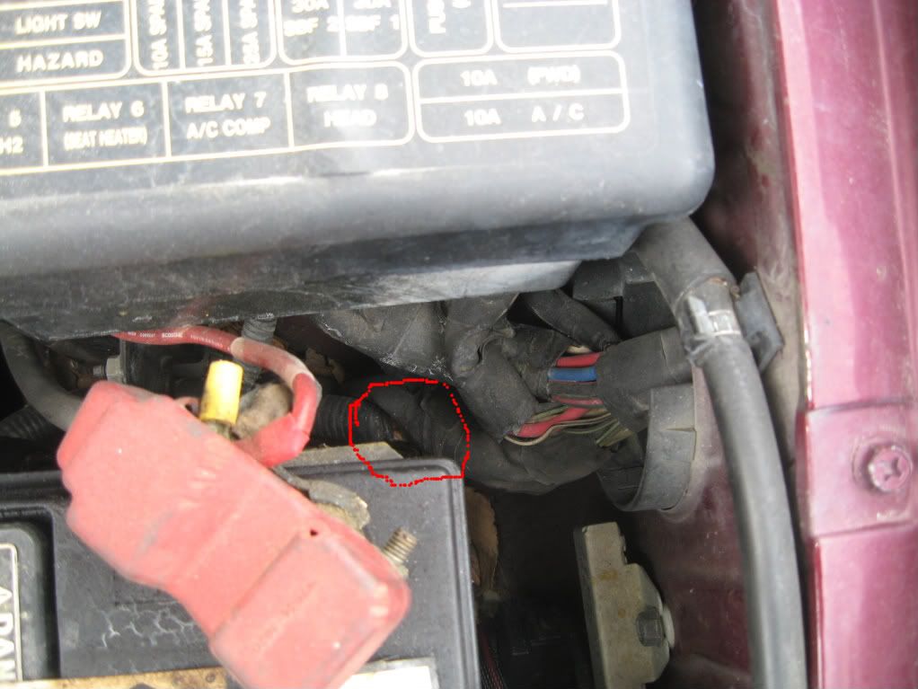
__________________
1997 Boudreaux LSi 1994 SVX LSi(SOLD) Kool Blue air filter, 4500k HID's, airbox mod, Hella horns, WRX 6 disc stereo, Infinity Reference and Clarion Pro Audio speakers, Infinity basslink sub, ECUtune Stage 1v5, ECUtune TCU, Power mode mod, Mad muffler mod v1.3 Last edited by svxcess; 12-03-2018 at 10:10 PM.
|
|
#7
04-02-2009, 02:41 PM
|
||||
|
||||
|
Re: FRESH START: Alternator Wiring Upgrade Configuration
Quote:
__________________
British vehicles are my last ditch attempt to keep the nasty Italian thoughts in my mind at bay. So far its working.
|
|
#8
04-02-2009, 02:58 PM
|
||||
|
||||
|
Re: FRESH START: Alternator Wiring Upgrade Configuration
Quote:
If the regulator fails, the fusible links will blow before damage can be done. Fusible links are rated by color (the same way that fuses are) the 14 gauge link will hwve a gray color to indicate its size-- this is the same color gray covering on the fusible link inside the fuse box in the engine compartment. .
__________________
. Subaru Ambassador 1996 Polo Green LSi #216..138,100 miles...SOLD JFICX8659TH100216.....Date of Manufacture: November 16, 1995..... Fuji Heavy Industries..Ōta North Plant....Ōta City,. Gunma Prefecture, Japan In-Service Date: January 2, 1997 "The Pristine Green Polo Machine First Polo Green on the Network First Clear front turn signals, JDM Alcyone hood emblem, rear panel, and BOXER engine cover on the Network (US) (2000) First 5000K HID factory fog lights (2007) First SVX JDM BBS wheels on a USDM SVX (2013) HID lighting (5000K) for headlight and H3 fog lights, PIAA SuperExtreme 120W high beams, rebuilt EG33 longblock, Cometic head gaskets, Phase II flexplate, AMR aluminum radiator with custom silicone hoses, 160A high-output alternator in aluminum-ceramic coated case, new design alternator wiring upgrade v.4, rare factory headlight protectors, refinished JDM BBS mesh aluminum wheels and custom, polished billet aluminum new hex center caps, LED grille mod, R1 Concepts high-carbon cryo slotted rotors, Akebono ceramic pads, Goodridge S/S braided brake lines, Smallcar Stage 1 shift kit, ThermalTech aluminum/ceramic-coated valve covers, Energy Suspension urethane front & rear swaybar bushings, Bontrager22 rear swaybar with QS Components Chromoly Teflon/Kevlar endlinks, "$15.00/5 minute" suspension mod. Hella Supertone horns, Custom stainless steel exhaust system with 2" headpipes, Magnaflow cats, AeroTurbine AR25 resonator /AWD "Bullet" muffler. R.I.P. 2010 Subaru Outback Limited 2.5 CVT...338,000 miles. Totaled by a 1,300 lb. COW March 4, 2016 2014 Hyundai Avante Limited ...178,000 miles. Actually quieter and smoother than the Outback 2007 Mazda Miata MX-5 PRHT...102,000 miles. Plenty of parts, service and windshields. 4th Registered Network member 2/21/2001 My NEW locker..I...My Email..I..Wikipedia/SVX . . Last edited by svxcess; 04-02-2009 at 03:38 PM.
|
|
#9
04-02-2009, 03:26 PM
|
||||
|
||||
|
My Understanding...
This is how I have come to understand alternator charging systems, making a comparison with something mechanical like an air compressor.
VOLTAGE (V) is a measure of electrical pressure. In a compressed air system, PSI (Pounds per Square Inch) is the measure of pressure. AMPERAGE (A) is a measure of electrical current flow. In the compressed air system, cubic feet of air is the similar measure of quantity. OHM (Ω) is the measure of resistance to electrical current flowa resistance holds back the flow of electrical current. In the compressed air system, restrictions, blockages, reduced passage (such as a metered orifice) are the terms most often used to describe the same effect that resistance will have in an electrical system. THE COMPARISON (explanation of system functions) The battery is an electrical storage reservoir, similar in function to the air tank for the compressed air system. (Actually, the battery does not store electricity, it would be more correct to say; the battery stores ingredients that can produce electricity.) Both the battery and the air tank can store a source of energy in reserve, keeping energy available for the times we need it. The alternator produces electrical power, which can operate devices that perform work. Similiar to the way the air compressor produces the compressed air, which can be used as a source of power to operate tools or machinery. The voltage regulator limits the maximum voltage in the electrical system. In the compressed air system, the pressure regulator limits the maximum pressure. The voltage regulator will also cause the alternator to produce more output, when voltage (pressure) at the electrical system is low. In the compressed air system, the pressure switch will turn on the compressor when system pressure gets low. Lights, ignition, A/C and accessories draw power from the electrical system. Every time we switch an accessory ON, more power is drawn from the system. Voltage (electrical pressure) drops as power is drawn from the system, and then the voltage regulator causes the alternator to make more current. In the compressed air system, an impact wrench, blowgun, paint gun, or the fitting for filling a tire, can all use power (compressed air) from the system. When we use compressed air from the system, PSI (air pressure) drops, and the regulator turns the compressor ON. In the electrical system, the voltage regulator turns the alternator "ON, or OFF as needed to maintain voltage at the proper level. And in the air compressor system the pressure regulator stops and starts the compressor as needed to maintain the proper level of pressure. An efficient electrical system will require an alternator that can produce an average of more output than we use, and the regulator will limit system voltage to the safe level we need. Like most machinery, the alternator cannot stand to work at maximum output for extended periods of time. Short bursts at maximum output are okay, but normal operation will require alternator operation at only a part of full output potential, most of the time. The alternator will generate power to operate the electrical system plus keep the battery charged. The purpose of the voltage regulator is to regulate the amount of power output from the alternator. The voltage regulator will allow the alternator to make enough power to maintain proper voltage level, but not allow system voltage to rise to a harmful level. With regulators for the alternator system, voltage-limiting is the means of controlling output. If the alternator was allowed to constantly produce all the power it could, system voltage would rise to a damaging level, the battery would overcharge, components would be damaged, and the alternator would soon overheat and burn out. With a 160amp alternator installed, you would not drive around with the alternator constantly producing 160amps. When driving one of our cars for example, with no accessories switched on and the battery topped off with a charge, the alternator produces only about 5 amps to 10 amps of current! (No matter how powerful the alternator, output is limited according to system demands.) When system voltage is below the setting of the voltage regulator, then the regulator causes the alternator to produce power until voltage reaches the maximum setting of the regulator. When we first crank up the engine, battery voltage will be at about 12.5 or 12.6 volts. The regulator recognizes low voltage, and causes the alternator to produce power. Also when driving, every time we switch an accessory ON, power is used from the system, voltage is lowered, and the regulator restores voltage by causing the alternator to make more power. This action automatically allows the alternator to provide power for the electrical system. The system does not need as much power output from the alternator when accessories are not using power, and when the battery is fully charged. When voltage at the system rises to about 14.2 volts, the voltage regulator begins limiting alternator output. When we switch an accessory OFF, use of power from the system is less, voltage quickly rises, and then the regulator will cause the alternator to make less power. ,
__________________
. Subaru Ambassador 1996 Polo Green LSi #216..138,100 miles...SOLD JFICX8659TH100216.....Date of Manufacture: November 16, 1995..... Fuji Heavy Industries..Ōta North Plant....Ōta City,. Gunma Prefecture, Japan In-Service Date: January 2, 1997 "The Pristine Green Polo Machine First Polo Green on the Network First Clear front turn signals, JDM Alcyone hood emblem, rear panel, and BOXER engine cover on the Network (US) (2000) First 5000K HID factory fog lights (2007) First SVX JDM BBS wheels on a USDM SVX (2013) HID lighting (5000K) for headlight and H3 fog lights, PIAA SuperExtreme 120W high beams, rebuilt EG33 longblock, Cometic head gaskets, Phase II flexplate, AMR aluminum radiator with custom silicone hoses, 160A high-output alternator in aluminum-ceramic coated case, new design alternator wiring upgrade v.4, rare factory headlight protectors, refinished JDM BBS mesh aluminum wheels and custom, polished billet aluminum new hex center caps, LED grille mod, R1 Concepts high-carbon cryo slotted rotors, Akebono ceramic pads, Goodridge S/S braided brake lines, Smallcar Stage 1 shift kit, ThermalTech aluminum/ceramic-coated valve covers, Energy Suspension urethane front & rear swaybar bushings, Bontrager22 rear swaybar with QS Components Chromoly Teflon/Kevlar endlinks, "$15.00/5 minute" suspension mod. Hella Supertone horns, Custom stainless steel exhaust system with 2" headpipes, Magnaflow cats, AeroTurbine AR25 resonator /AWD "Bullet" muffler. R.I.P. 2010 Subaru Outback Limited 2.5 CVT...338,000 miles. Totaled by a 1,300 lb. COW March 4, 2016 2014 Hyundai Avante Limited ...178,000 miles. Actually quieter and smoother than the Outback 2007 Mazda Miata MX-5 PRHT...102,000 miles. Plenty of parts, service and windshields. 4th Registered Network member 2/21/2001 My NEW locker..I...My Email..I..Wikipedia/SVX . .
|
|
#10
04-02-2009, 06:17 PM
|
|||
|
|||
|
John I think you need an option D
Remove the two white wires from the alternator output post, shorten them back, and join them together. Don"t connect them to anything as they are already connected to the battery through the fusible link. The alternator is connected through your new wire and fuse to the battery. It would look like this.,  The ignition wiring that was connected to the alternator, now is connected through the standard fusible link, to the battery. This isolates the alternator output from the rest of the system wiring, so in the event that the regulator loses control of the alternator voltage, it won't harm anything from the higher voltage. Harvey.
__________________
One Arm Bloke. Tell it like it is! 95 Lsi. Bordeaux Pearl, Aust. RHD.149,000Kls Subaru BBS wheels. 97 Liberty GX Auto sedan. 320,000Kls. 04 Liberty 30R Auto Premium. 92.000kls. Last edited by svxcess; 12-04-2018 at 09:07 PM.
|
|
#11
04-02-2009, 06:22 PM
|
||||
|
||||
|
Re: FRESH START: Alternator Wiring Upgrade Configuration
Quote:
__________________
British vehicles are my last ditch attempt to keep the nasty Italian thoughts in my mind at bay. So far its working.
|
|
#12
04-02-2009, 06:23 PM
|
||||
|
||||
|
Re: FRESH START: Alternator Wiring Upgrade Configuration
Benebob,
I sent Christian Caudle, in Technical Engineering at Maniac Electric Motors in dallas, TX (Where my high-output altermator was built) a compilation of the last few posts and replies between you and I. I was expressing your concern over what I was doing and asked her for some guidance as to which of us was correct. This is one fine lady who took offense at the "trust me your regulator and/or alternator will fail much more often then a standard output alternator will." It's like bad-mouthing one of her children. Here are email replys to me in regards to this. Re: Alternator concerns from members From: christian caudle (christian@maniacelectricmotors.com) Sent: Thu 4/02/09 6:15 PM To: JOHN HOFFMAN (jhoffman44@hotmail.com) Well, John sometimes you must give-up. Just like when you own a company and must unfortunately fire employees, sometimes you must fire customers or potential customers. A vehicle that has an electrical load of 35 Amps at 600 RPMs - That is what the alternator will supply, even though it may be capable of 37 Amps. If the RPM increases to 2000 RPM, but electrical load stays steady at 35 Amps then the alternator will produce 35 Amps EVEN THOUGH its capabilities are maybe 180 Amps. In todays vehicles if the regulator is not inside the alternator then the Computer controls regulation and has the same function at ALL speeds. It measures loads and adjust the field current to maintain 14-14.5 Volts. You are correct and there is no way you can educate someone that "knows more" no-matter-what. I don't even understand this guys concerns. There is no run-away amps. and "wire before the link"?? Grounds and shorts can cause high amperage through any circuit involved, causing problem with wiring up to 'circuit protecting' fuses and links, but that doesn't matter what kind of alternator is installed. If the regulator fails and voltage increases, then amps will decrease, no matter what kind of alternator is installed. I learn more everyday and gravitate to people that are smarter than me. And I avoid people who know everything. Thanks for the effort John and all the great information you are giving me, I hope to have time tonight to get this posted online and improve our own web site. Re: Alternator From: christian caudle (christian@maniacelectricmotors.com) Sent: Thu 4/02/09 6:17 PM To: JOHN HOFFMAN (jhoffman44@hotmail.com) Can you please send me a link to this forum? Why in the world are all the wonderful SVX guys letting him badger you with nonsense. Re: Alternator From: christian caudle (christian@maniacelectricmotors.com) Sent: Thu 4/02/09 6:23 PM To: JOHN HOFFMAN (jhoffman44@hotmail.com) We sell about 2-6 high-output alternators per day and there are numerous other wonderful competitors doing the same thing. There is probably 33 million audio and accessory enthusiasts out there running high-output alternators. Someone needs to open up those hoods and point out to these unknowing consumers all the burnt-up wires and fuses that they are victims of! As Christian said, if a regulator fails, voltage increases to the battery and may fry it, but the the amps will decrease. Most of the time when a regulator of this type fails, it burns to an open circuit, at which point everything just stops. She is a very nice woman who is extremely knowledgable about what she does. Give her a ring at 972-557-5678 if you care to tangle with her further. I have no dog in this fight... but my money is on Christian. .
__________________
. Subaru Ambassador 1996 Polo Green LSi #216..138,100 miles...SOLD JFICX8659TH100216.....Date of Manufacture: November 16, 1995..... Fuji Heavy Industries..Ōta North Plant....Ōta City,. Gunma Prefecture, Japan In-Service Date: January 2, 1997 "The Pristine Green Polo Machine First Polo Green on the Network First Clear front turn signals, JDM Alcyone hood emblem, rear panel, and BOXER engine cover on the Network (US) (2000) First 5000K HID factory fog lights (2007) First SVX JDM BBS wheels on a USDM SVX (2013) HID lighting (5000K) for headlight and H3 fog lights, PIAA SuperExtreme 120W high beams, rebuilt EG33 longblock, Cometic head gaskets, Phase II flexplate, AMR aluminum radiator with custom silicone hoses, 160A high-output alternator in aluminum-ceramic coated case, new design alternator wiring upgrade v.4, rare factory headlight protectors, refinished JDM BBS mesh aluminum wheels and custom, polished billet aluminum new hex center caps, LED grille mod, R1 Concepts high-carbon cryo slotted rotors, Akebono ceramic pads, Goodridge S/S braided brake lines, Smallcar Stage 1 shift kit, ThermalTech aluminum/ceramic-coated valve covers, Energy Suspension urethane front & rear swaybar bushings, Bontrager22 rear swaybar with QS Components Chromoly Teflon/Kevlar endlinks, "$15.00/5 minute" suspension mod. Hella Supertone horns, Custom stainless steel exhaust system with 2" headpipes, Magnaflow cats, AeroTurbine AR25 resonator /AWD "Bullet" muffler. R.I.P. 2010 Subaru Outback Limited 2.5 CVT...338,000 miles. Totaled by a 1,300 lb. COW March 4, 2016 2014 Hyundai Avante Limited ...178,000 miles. Actually quieter and smoother than the Outback 2007 Mazda Miata MX-5 PRHT...102,000 miles. Plenty of parts, service and windshields. 4th Registered Network member 2/21/2001 My NEW locker..I...My Email..I..Wikipedia/SVX . . Last edited by svxcess; 12-04-2018 at 09:14 PM.
|
|
#13
04-02-2009, 06:30 PM
|
||||
|
||||
|
Re: FRESH START: Alternator Wiring Upgrade Configuration
Quote:
Just join them to each other and start the car? .
__________________
. Subaru Ambassador 1996 Polo Green LSi #216..138,100 miles...SOLD JFICX8659TH100216.....Date of Manufacture: November 16, 1995..... Fuji Heavy Industries..Ōta North Plant....Ōta City,. Gunma Prefecture, Japan In-Service Date: January 2, 1997 "The Pristine Green Polo Machine First Polo Green on the Network First Clear front turn signals, JDM Alcyone hood emblem, rear panel, and BOXER engine cover on the Network (US) (2000) First 5000K HID factory fog lights (2007) First SVX JDM BBS wheels on a USDM SVX (2013) HID lighting (5000K) for headlight and H3 fog lights, PIAA SuperExtreme 120W high beams, rebuilt EG33 longblock, Cometic head gaskets, Phase II flexplate, AMR aluminum radiator with custom silicone hoses, 160A high-output alternator in aluminum-ceramic coated case, new design alternator wiring upgrade v.4, rare factory headlight protectors, refinished JDM BBS mesh aluminum wheels and custom, polished billet aluminum new hex center caps, LED grille mod, R1 Concepts high-carbon cryo slotted rotors, Akebono ceramic pads, Goodridge S/S braided brake lines, Smallcar Stage 1 shift kit, ThermalTech aluminum/ceramic-coated valve covers, Energy Suspension urethane front & rear swaybar bushings, Bontrager22 rear swaybar with QS Components Chromoly Teflon/Kevlar endlinks, "$15.00/5 minute" suspension mod. Hella Supertone horns, Custom stainless steel exhaust system with 2" headpipes, Magnaflow cats, AeroTurbine AR25 resonator /AWD "Bullet" muffler. R.I.P. 2010 Subaru Outback Limited 2.5 CVT...338,000 miles. Totaled by a 1,300 lb. COW March 4, 2016 2014 Hyundai Avante Limited ...178,000 miles. Actually quieter and smoother than the Outback 2007 Mazda Miata MX-5 PRHT...102,000 miles. Plenty of parts, service and windshields. 4th Registered Network member 2/21/2001 My NEW locker..I...My Email..I..Wikipedia/SVX . .
|
|
#14
04-02-2009, 06:35 PM
|
||||
|
||||
|
Re: My Understanding...
Quote:
Note that any resistance to flow will use energy and produce heat. An important fact, which is also illustrated as a common denominator in both systems. However, with air or water as representations, the source of transferable power is simply exhausted as waste, on completion of the work involved. Whereas a flow of electricity requires a return path. This does add a complication which must be taken into account and catered for, within any electrical system. Thanks are due to you for posting the quoted write up.
__________________
Trevor, New Zealand. As a child, on cold mornings I gladly stood in cowpats to warm my bare feet, but I detest bull$hit!
|
|
#15
04-02-2009, 07:29 PM
|
||||
|
||||
|
Re: FRESH START: Alternator Wiring Upgrade Configuration
Quote:
Post #63 dated Ist April, 2009. I now detail my recommendation for best possible arrangement as a final offering within a thread which has become a frustrating waste of time:- Fit a heavier main charging circuit conductor if such is desired, incorporating a suitable inline fuse close to any direct connection to the battery. Ensure that a separate voltage sensing conductor (only a fairly light gauge is required) is installed from alternator connection 2, direct to the battery or battery circuit. This circuit should be fused battery end, at 10 amps, i.e. over rated as a safety measure. Provided the voltage sensing circuit is intact, there will be no run away of the alternator. It will be best if the battery connection is made at the fuse box and to the incorporated distribution bus bar connection point. There mast be an existing wire so connected, which can be used, so that accessing the fuse box is not required. This will achieve a tidy workmanlike job, without multiple connections to the battery terminal. A separate conductor is required between the protected end of the fusible link, i.e. via fuse box terminal 1, bridged to terminal 2. and SBF holder terminal 2. The facility for these connections will surely exist, but will require sorting and possible amendment. Unfortunately I have not been in a position to outline in detail all required alterations, as I have not had exact information covering the factory installation.
__________________
Trevor, New Zealand. As a child, on cold mornings I gladly stood in cowpats to warm my bare feet, but I detest bull$hit!
|
 |
|
|


 Linear Mode

