
Live Chat!
SVX or Subaru Links
Old Lockers
Photo Post
How-To Documents
Message Archive
SVX Shop Search
|
SVX Network Forums Live Chat! SVX or Subaru Links Old Lockers Photo Post How-To Documents Message Archive SVX Shop Search |
IRC users: |
|
#1
 05-30-2007, 11:21 PM
|
||||
|
||||
|
Electrics Once Again
Splitting this topic from my old one because the old one focused on turn signals doing strange things, and right now that's not what I'd like to focus on (as all the evidence points to...nothing being wrong).
Instead, I'd like to turn my attention to the problem of missing backlight illumination. I ran an experiment a day ago in which I connected a new bulb to the shift column and turned the headlights on. The new bulb did not illuminate. This leads me to believe that it is not the bulbs in the backlights that are blown, but it is instead either a broken part of the electrical system, or an error in the wiring. Either one is likely. However, where is a place to start? Trevor, I guess I'm once again calling upon your years of diagnostics expertise. Where should I begin hunting down current to the backlighting? I'd much rather find out exactly what's wrong than go about replacing random things... I have a hunch that the answer lies in the turn signal stalk. But it is nothing more than a hunch; it's not backed up by any experimental testing. Awaiting response with multimeter in hand, Nomake 
|
|
#2
05-31-2007, 07:08 AM
|
|||
|
|||
|
Quote:
To summarise, you found that you had approximately double the voltage drop when the indicator switch was moved, compared with the using hazard switch. I would have thought you would have realised that it should have halved the current demand because you are only lighting half the number of lamps. Did you not wonder where the additional current load was going? I thought that your throw away comment that the fans speeded up at the same time as you moved the indicator switch might have given you half a clue as to what might be wrong  . .Quote:
 Then it's just a matter of checking that you get the voltages you expect on each of the wires ..... you have downloaded the wiring diagrams, haven't you?
__________________
I often say that when you can measure what you are speaking about, and express it in numbers, you know something about it; but when you cannot measure it, when you cannot express it in numbers, your knowledge is of a meagre and unsatisfactory kind; it may be the beginning of knowledge, but you have scarcely in your thoughts advanced to the state of Science, whatever the matter may be. Sir William Thomson
|
|
#3
05-31-2007, 08:41 AM
|
||||
|
||||
|
Quote:
As this is not affecting actual driveability, I have decided to put it on the back burner. And focus on one that is affecting [night] driveability. Quote:
After that, the best I can guess is that they make their way somehow to pins C1 and C8 on the instrument panel (as those are the only listed illuminations for the panel) via the InstPanel Light Switch (impossible; it goes through the Time Control Unit) and Fuse #9. Also, the illumination for the Power Windows merely says "IntPnl SW Lts." Again, how? Time Control Unit is in the way. In fact, all of the lamps in the diagram which do not work in my car point to "I/P SW LTS." I read this as "Instrument Panel Switch Lights," but am I wrong? Now, the Time Control Unit also runs the clock, seatbelts and windshield wipers (albeit a little indirectly), and all of those function properly as well, so this "Time Control Unit" is not a likely culprit, I don't think. Wait... ah HA! I found the missing piece. Silly me, I was on the wrong diagram. ALL of the lights that do not function in my car are found in Figure 8, Sections E29-E31. Glove box light, Cig Lighter light, (cd+radio light? There is one? or is it gone because I'm aftermarket?), climate control backlight, power mirror backlight, mirror defrost backlight, shifter select backlight, rear defroster backlight. I have no clue what "SW BOX ASSY IN/OUT LT" are, but I guess they don't work either (backlights for the security, cruise and hazard switches?). Interestingly, the Shift Select Lever Illum seems to come from the Spot/Room lights, which DO work. Also, this adds pin 20 or the Time Control Unit to the list of connections in the Illum circuit... Where the heck is the detail for the Time Control Unit!? Last edited by Nomake Wan; 05-31-2007 at 08:43 AM.
|
|
#4
05-31-2007, 09:49 AM
|
|||
|
|||
|
I quote what you said in the other thread
Quote:
I don't know ..... but it seems distinctly possible that there is some other circuit path being made when you move that switch which is taking a serious amount of current. As to the other problem, if you suspect the switch, why not test the switch? Use the wiring diagram to identify the inputs/outputs. If the inputs are OK but the outputs aren't then you have located your problem. As the panel lights are a problem then I would concentrate on the rheostat adjustment first. I think that you'll find that the time control unit is a red herring.
__________________
I often say that when you can measure what you are speaking about, and express it in numbers, you know something about it; but when you cannot measure it, when you cannot express it in numbers, your knowledge is of a meagre and unsatisfactory kind; it may be the beginning of knowledge, but you have scarcely in your thoughts advanced to the state of Science, whatever the matter may be. Sir William Thomson
|
|
#5
06-05-2007, 03:15 PM
|
||||
|
||||
|
Now have photos of the steering assembly. Not surprisingly, it looks as if someone has been under there once; there is a bent piece of plastic on one of the steering wheel covers and the harness thingy is held together with a ziptie and feels cheap.
   The first thing which jumped out at me was the black connector on the bottom. It has five wires going in one side, and three coming out the other. That doesn't seem right. Anyway, I still have the car disassembled... hoping someone can look at those photos and tell me which wiring harness is for the lighting. 
|
|
#6
06-05-2007, 04:55 PM
|
||||
|
||||
|
Which connector are you referring to?
__________________
Subaru ECU and TCU Website 1992 Alcyone SVX Version L 1992 Alcyone SVX Version L 1994 Alcyone SVX S40-II 2004 Subaru Legacy 2.5 SE Sports Tourer 1996 Subaru Legacy 2.2 GX Wagon 1988 Subaru Justy J12 SL-II Last edited by b3lha; 06-05-2007 at 05:04 PM.
|
|
#7
06-05-2007, 05:18 PM
|
||||
|
||||
|
Quote:
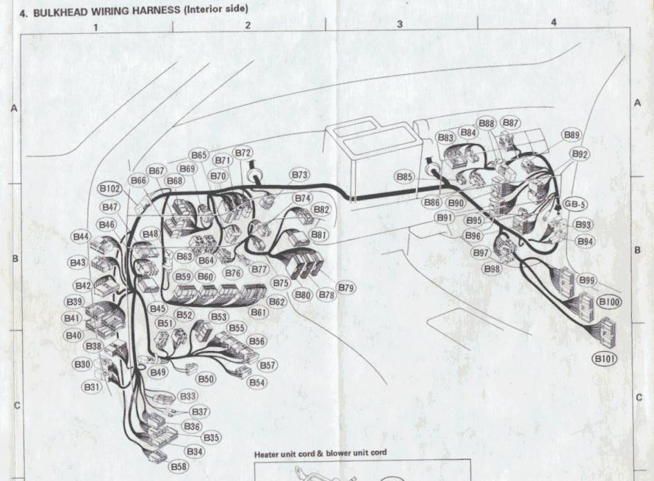
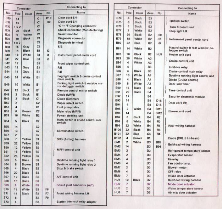
From what I can see, those lights you mentioned are always connected to power from fuse no.9 - a red wire which goes to B41 pin 7 and B80 pin 8 and B99 pin 5. You should check all these are live. The time control unit switches these lights on by connecting the wire that goes into pin 20 (Connector B91) to ground. You could try grounding that wire yourself and seeing if the lights come on.
__________________
Subaru ECU and TCU Website 1992 Alcyone SVX Version L 1992 Alcyone SVX Version L 1994 Alcyone SVX S40-II 2004 Subaru Legacy 2.5 SE Sports Tourer 1996 Subaru Legacy 2.2 GX Wagon 1988 Subaru Justy J12 SL-II Last edited by b3lha; 06-05-2007 at 05:27 PM.
|
|
#8
06-05-2007, 08:42 PM
|
||||
|
||||
|
I've been looking at these diagrams:
http://seccs.org/tech/manuals/1992_S...G_DIAGRAMS.pdf But yours have graphical representations, I like that.  B54 is the harness I'm talking about which begins in five wires and comes out the other side with three. So that's not it.
|
|
#9
06-06-2007, 02:09 PM
|
||||
|
||||
|
Well, went about checking things... found interesting results...
The blue connector, B41, does indeed have a control for illumination. Since when it was unplugged the headlights and such would come on, but the dash lights would not dim. So that means the dimmer diode is also connected to B41... Now, I took my trusty multimeter and turned it to current, then put one probe in B41 pin 7 and put the other probe onto the pin on the other side which goes into pin 7 but got nothing. I'm guessing the connector has to be connected for current to flow? If so, how do I go about checking that these wires are live? And I THINK I got pin 7 right... but which one's pin 7 exactly...? (there are a few red wires) I also found the other blue connector (B80) but it's a little harder to get to. I can still get at it but I'd like to know what I'm doing beforehand. I also took apart the glove compartment and found the time control unit (88001PA000 which SubaruParts incorrectly lists as the Transmission Control Unit) and the two wiring harnesses that go into it, the 16-pin and 20-pin. On the 20-pin, which is pin 20? I always have a hell of a time trying to figure out which pin is which and would rather not ground the wrong one, you know? Is there a universal rule for knowing what pin is what number by looking at the harness? Like, "start in left corner on top with latch facing up" or something? Thanks. Will keep the car apart until I've solved this mystery!! EDIT: Oh yeah, and I know that Fuse 9 works as it should because the dimmer diode (that dims the clock, shift indicator, POWER light, etc) does not function without it in place. Last edited by Nomake Wan; 06-06-2007 at 02:24 PM.
|
|
#10
06-06-2007, 04:54 PM
|
||||
|
||||
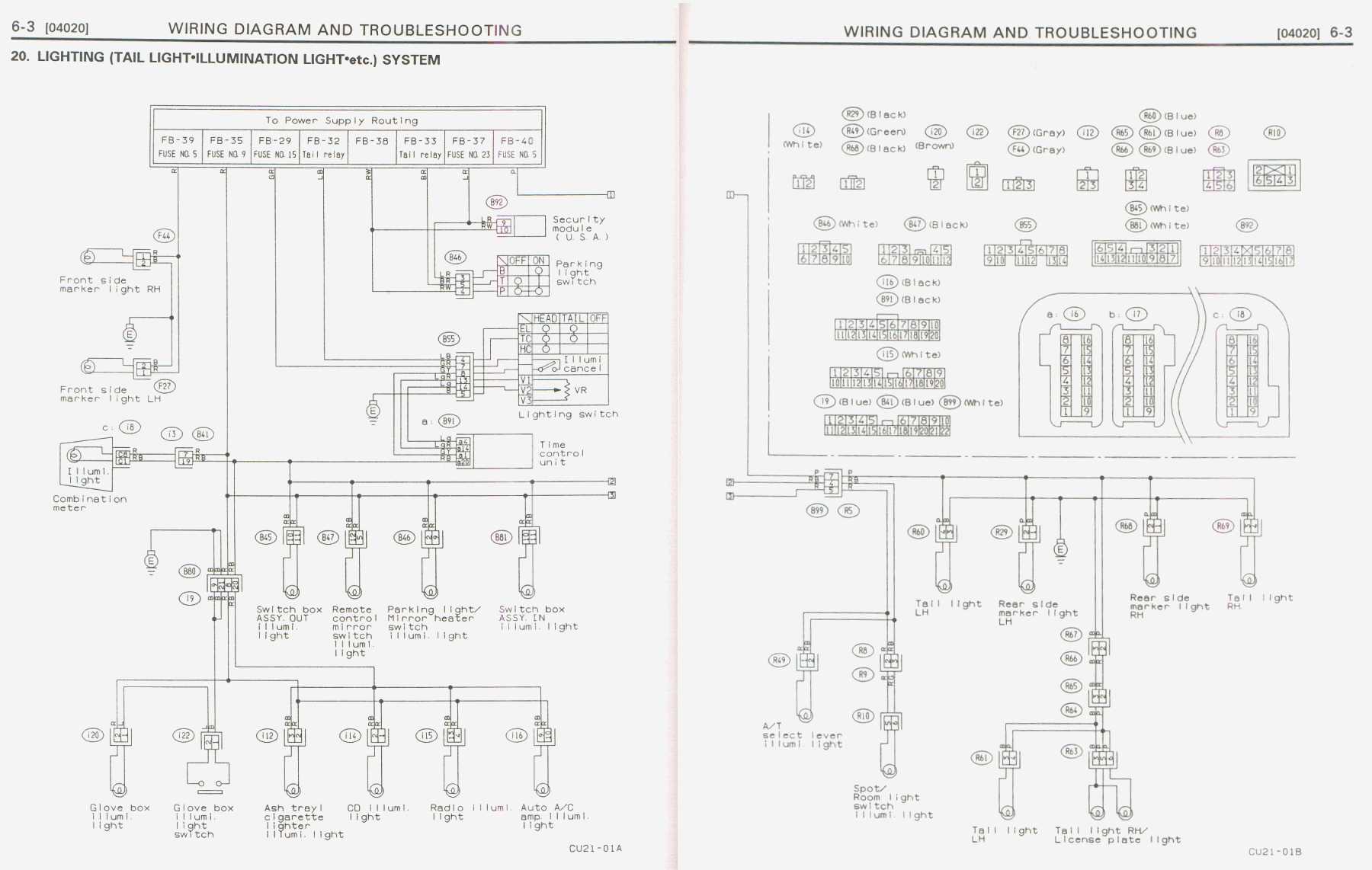 This diagram is a little easier to follow than yours. Sorry it's so big, I wanted to make sure it was readable. You can see the pin numberings for each connector on the top left. You are right in your assumption: On the female side, latch up, start at the top left. On the male side it's obviously reversed. I suggest checking the red power wire at each connector in the circuit to ensure that it is live. Select voltage on your meter, put the red probe to the pin you want to test and the black probe to a ground. The time control unit switches the lights on by grounding the red/black wire. If the lights all have power then the problem must be on the ground side. The time control unit switches the lights on by grounding the red/black wire. Actually, it's a duty cycle. The time control unit varies the brightness of the lights by pulsing the red/black wire to ground very rapidly. The duty cycle varies from 12 to 100% depending on the position of the dimmer switch.
__________________
Subaru ECU and TCU Website 1992 Alcyone SVX Version L 1992 Alcyone SVX Version L 1994 Alcyone SVX S40-II 2004 Subaru Legacy 2.5 SE Sports Tourer 1996 Subaru Legacy 2.2 GX Wagon 1988 Subaru Justy J12 SL-II Last edited by b3lha; 06-06-2007 at 05:00 PM.
|
|
#11
06-06-2007, 05:50 PM
|
||||
|
||||
|
GUESS WHAT! I HAVE ILLUMINATION!!!!
I did a very badly rigged setup where I used that same diagnostic grounding cable as a ground, and again jammed a wire in the back of the harness. Pin 20, B91. But as soon as I turn the car on... BAM! Lights!! All the lights that didn't work lit right up. Every single one!!! So, where does this lead? I grounded Pin 20 and I got lights. So where's the fault?
|
|
#12
06-06-2007, 06:34 PM
|
||||
|
||||
|
I was hoping that might happen.
The time control unit switches those lights on and off by connecting them to ground. As I said, it's a duty cycle controlled by the dimmer knob. I would say the problem is either the time control unit, the dimmer knob, or the connections. First check the grounds on the time control unit. It can't switch the lights to ground if it has no ground. That would be 12 and 13 of B91, both black. Check the resistance between them and a known good ground. It should be 0 or thereabouts. If that is successful, eliminate the dimmer knob by jamming a wire into the back of 4 and 14 (LightGreen and LightGreen/Red) of B91 to simulate the knob being at max. If the lights come on then the problem is the knob or its wiring. Alternatively you could unplug B91 and measure the resistance between those two pins and see it change as you turn the dimmer knob. To be honest, my money is on the final option of your time control unit being faulty. Possibly someone connected something that overloaded one of the circuits and damaged some of its internals. I've never actually seem one. Can it be opened and checked for anything that looks overheated, or is a sealed unit?
__________________
Subaru ECU and TCU Website 1992 Alcyone SVX Version L 1992 Alcyone SVX Version L 1994 Alcyone SVX S40-II 2004 Subaru Legacy 2.5 SE Sports Tourer 1996 Subaru Legacy 2.2 GX Wagon 1988 Subaru Justy J12 SL-II Last edited by b3lha; 06-06-2007 at 06:38 PM.
|
|
#13
06-06-2007, 06:51 PM
|
||||
|
||||
|
It's a sealed unit, but I'm going to have to disagree with you. The other functions of the time control unit all function as they should. I don't have another one around to test, but my money is all in on the dimmer switch on the turn signal stalk.
Because the turn signal gives me problems. And they're on the same stalk. 1+1 should equal 2. I pray it does. If so, I just gotta find a combination switch or a replacement turn signal stalk, then figure out how to re-wire the sucker. I'll do those tests tomorrow. It's dark and cold outside right now. ")
|
|
#14
06-06-2007, 07:43 PM
|
||||
|
||||
|
Quote:
__________________
Trevor, New Zealand. As a child, on cold mornings I gladly stood in cowpats to warm my bare feet, but I detest bull$hit! 
|
|
#15
06-06-2007, 08:24 PM
|
||||
|
||||
|
Yeah, sorry about that. Those who come late to the party are often confused as to the party's status.
Thanks for the thought though. Hopefully tomorrow everything'll be sorted out. EDIT: I wish I had a better camera with a slower shutter speed, but here's the best pic I could get. I'm so happy to see those lights. 
Last edited by Nomake Wan; 06-06-2007 at 09:35 PM.
|
 |
|
|


 Linear Mode

