
Live Chat!
SVX or Subaru Links
Old Lockers
Photo Post
How-To Documents
Message Archive
SVX Shop Search
|
SVX Network Forums Live Chat! SVX or Subaru Links Old Lockers Photo Post How-To Documents Message Archive SVX Shop Search |
IRC users: |
|
|
|
#1
 11-02-2006, 08:10 PM
|
|||
|
|||
|
4EAT Line Pressure control.
The oil pressures that act in the Auto box are a number of different pressures that are all derived from the oil pump pressure that is called the Line Pressure. The engine drives the oil pump, and its output varies with the engine speed. To prevent the pressure from becoming too high at high engine speeds, the Pressure Regulator valve controls the line pressure.
This valve is not just a pressure bleed off type. It is a valve that controls the pumps output, by moving the pumps cam ring to change the volume output, from full output, to no output. As the pump pressure builds up, the Regulator valve sends more pressure to the cam ring to reduce the pumps output. In this way the maximum line pressure is held to about 215 psi, but as the engine speed varies, so does the line pressure, reducing to about 70 psi at idle. The Regulator valve also adjusts for the sudden variations in Line pressure caused by the application of clutches, bands and valve action. As the Line pressure varies with engine speed, so does the engines torque, so it is not a problem to have the pressure low with low engine speeds. As the engine speed and torque increases, the pressure increases. If the engine is at part throttle and at high speed, there is no need for a high Line pressure as the torque is low. To save power the Line pressure is adjusted to suit the throttle position. This is performed by the Duty solenoid A. The A solenoid is a controllable valve that can vary a Pilot pressure applied to the Regulator valve, to alter the Line pressure, under the control of The Transmission Control Unit. The TCU controls the pressure for oil temp, throttle position and gear shifting. The TCU turns the Throttle Position Sensors 0 to 12V signal, into a 12V Duty Cycle signal that varies the current sent to the Solenoid, in line with the throttle position. When full throttle is used, the solenoid stays as an open drain, and the pressure is held high. As the throttle is closed the Throttle Duty Cycle current, is increased to reduce the solenoids drain on the Pilot pressure that acts on the Regulator Pressure Modifier valve and Line pressure is reduced. 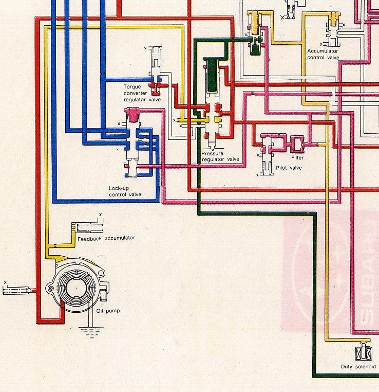 The way the TCU controls the Line Pressure for oil temp or gear shifting, is done by the A solenoid valve, through a different wire that connects directly to the A solenoid, without going through the Dropping resistor. As the Throttle Position Duty Cycle is a 12V signal and the A Solenoids resistance is only 3 ohms, the Dropping resistor is used to drop the current to a level that the solenoid can use. The other signal from the TCU is a 5V Duty Cycle that is fed in to the line, between the dropping resistor and the solenoid. This forms a voltage divider circuit, so that both signals can be sent to the Solenoid at the same time. So that when the throttle is wide full open and the line pressure is high, the TCU can send a signal through the other line to reduce the line pressure while the box changes gear, or for a number of other conditions. This is what the circuit looks like with both TCU signals feed to the solenoid.  So while the Throttle pressure is controlled by the throttle pedal position. The Line Pressure is modified by the TCU to suit the operating conditions that apply at the time. Harvey. 
__________________
One Arm Bloke. Tell it like it is! 95 Lsi. Bordeaux Pearl, Aust. RHD.149,000Kls Subaru BBS wheels. 97 Liberty GX Auto sedan. 320,000Kls. 04 Liberty 30R Auto Premium. 92.000kls. Last edited by oab_au; 11-04-2006 at 07:01 PM. 
|
|
#2
11-03-2006, 02:20 AM
|
||||
|
||||
|
Interesting.
Are the two duty cycles the same frequency, and if so, are they in phase or out of phase?
__________________
Subaru ECU and TCU Website 1992 Alcyone SVX Version L 1992 Alcyone SVX Version L 1994 Alcyone SVX S40-II 2004 Subaru Legacy 2.5 SE Sports Tourer 1996 Subaru Legacy 2.2 GX Wagon 1988 Subaru Justy J12 SL-II
|
|
#3
11-03-2006, 05:00 PM
|
|||
|
|||
|
Quote:
 I would think that they are at the same frequency, as they are working the same armature, and would be in phase. Other wise they would cancel each other out. Harvey.
__________________
One Arm Bloke. Tell it like it is! 95 Lsi. Bordeaux Pearl, Aust. RHD.149,000Kls Subaru BBS wheels. 97 Liberty GX Auto sedan. 320,000Kls. 04 Liberty 30R Auto Premium. 92.000kls.
|
|
#4
11-03-2006, 11:37 PM
|
|||
|
|||
|
Didn't explain that very well Phil.
As usual I didn't explain that very well.
 The signal coming from the TCU G/R, pin c8 to the dropping resistor is a zero to 12 volt Duty Cycle. The signal coming from the TCU G/Y, pin c7, is a zero to 5 volt Duty Cycle. The two can be in phase, as by the time the two signals meet, between the resistor and the solenoid, the dropping resistor has reduced the 0v to 12v to the same, zero to 5V, for the other TCU line. I would imagine that this line would always have a 'driving' current on it. to close the solenoid and reduce the line pressure. I can't see a reason for it to have a 'no drive' signal that might conflict with a 'drive' signal on the Throttle line. So it would always only have to raise the current level, regardless of the throttle level. Harvey.
__________________
One Arm Bloke. Tell it like it is! 95 Lsi. Bordeaux Pearl, Aust. RHD.149,000Kls Subaru BBS wheels. 97 Liberty GX Auto sedan. 320,000Kls. 04 Liberty 30R Auto Premium. 92.000kls.
|
|
#5
11-04-2006, 04:12 AM
|
||||
|
||||
|
Harvey,
Your unsolicited post has no other purpose than to instruct. Therefore members should take heed with much caution. You are stating explicitly that when the resistor circuit is disconnected, the only control signal present is at a maximum potential of five volts. What you outline would indicate that you also continue to believe that the A solenoid is held stationary at intermediate positions in order to control pressure. Is this so ? You state :- So while the Throttle pressure is controlled by the throttle pedal position. The Line Pressure is modified by the TCU to suit the operating conditions that apply at the time. Please clarify exactly what is "throttle pressure". Your opening statements suggest that you believe the major duty in respect of line pressure control is carried out hydraulically/mechanically in line with earlier designs and control via the A solenoid valve is a secondary feature. But here you agree line pressure is modified by the TCU, to suite operating conditions. I contend that the transmission is designed such that line pressure, is in all operative modes, electrically / electronically controlled via the TCU, fail safe features accepted.
__________________
Trevor, New Zealand. As a child, on cold mornings I gladly stood in cowpats to warm my bare feet, but I detest bull$hit!
|
|
#6
11-04-2006, 11:44 AM
|
|||
|
|||
|
Trevor,
I don't intend to get in the middle of your 'pissin' match, so please don't dump on me, but this seems to be Harvey's thread. It would seem in fact, that it is your post that is 'unsolicited'. I'm not aware that one need be 'solicited' to begin a thread, as Harvey has done here. Perhaps it best for all that you initiate a separate thread to discuss your views. Quote:
__________________
Special Thanks to Our Friends and Sponsors: * http://www.alcyone.org.uk/ssm  http://www.PhenixWheels.com http://www.dba.com.au/ http://www.ClassicSoftTrim.com http://ToyoTires.com/tire/pattern/versado-lx Gillman Subaru of Houston "QuickChange" http://www.TransGo.com/ http://www.PlanetSVX.com Bontrager Works, http://www.PhenixWheels.com http://www.dba.com.au/ http://www.ClassicSoftTrim.com http://ToyoTires.com/tire/pattern/versado-lx Gillman Subaru of Houston "QuickChange" http://www.TransGo.com/ http://www.PlanetSVX.com Bontrager Works, '92 Subaru SVX LS-L Claret ORIGINAL OWNER '92 LS-L Pearl~ '92 LS Pearl~ '92 LS-L Teal~ '92 LS-L Silver~ '95 LSi Polo~ '92 JDM Alcyone SVX Version-L 4WS Pearl~ http://www.subaru-svx.net/forum/showthread.php?t=54143 '92 JDM Alcyone SVX Version-L 4WS Ebony~ http://www.subaru-svx.net/forum/showthread.php?t=54117
|
|
#7
11-04-2006, 05:30 PM
|
|||
|
|||
|
Quote:
Harvey...
__________________
One Arm Bloke. Tell it like it is! 95 Lsi. Bordeaux Pearl, Aust. RHD.149,000Kls Subaru BBS wheels. 97 Liberty GX Auto sedan. 320,000Kls. 04 Liberty 30R Auto Premium. 92.000kls.
|
|
#8
11-06-2006, 05:31 PM
|
||||
|
||||
|
Quote:
Your unsolicited (unrequested, not asked for) post has no other purpose other than to instruct. i.e. This constitutes a brief, straightforward, explanatory opening statement of a fact, complimentary to that which was to follow. It would appear that many are unable to decipher good English. I now appears that I have to add that which should have been patently obvious. -------- to instruct, or as is more likely, to obtusely negate posted statements, as they have recently been confirmed as having being made a permanent record. ------------------ DUTY SOLENOID A. A pulse width modulated duty solenoid valve, ( Sometimes known as a pulsoid), as is incorporated in the SVX transmission control system, adjusts pressure in the following manner :- The fluid line is provided with a bleed or bypass via an on/off device in the form of an electrically operated valve. This solenoid valve is opened and closed repeatedly, in a rhythmical manner by a control current which is turned very rapidly on and off by the transmission control unit (TCU). The valve is a normally closed device, and remains closed in the event of the loss off a control current. After passing through this modulated solenoid valve, the continually interrupted pressure is in the form of a pulsed flow. When the peaks level off with the troughs there is a resulting overall steady reduced pressure. The level of this pressure is adjusted by varying the on/off intervals. Most often the length of the on time is adjusted and the number of on/off pulses per second is kept constant. The usual rate is around 50 cycles per second. The resulting adjusted output pressure is therefore delivered as a fluctuating stream. The system incorporates an expansion chamber as a smoothing element, which works as a sort of cushion. This device is usually in the form of a cylinder and piston or diaphragm, backed by a coil spring. In the SVX system the component is described as a Pressure Modifier Accumulator. The high pressure peaks in the stream press the piston outwards and become rounded off, while the low pressure troughs are filled in as a result of the piston moving inwards under spring pressure. The end result is a smoother level of pressure, such that controlled devices are not materially affected. An increase in the volume controlled is achieved by transferring the solenoid regulated pressure to a pressure modifier valve and a regulator valve. It should be clear that by chopping the fluid supply in an adjustable way, pressure control is achieved economically using a simple poppet type solenoid valve, with few mechanical or electrical complications. However the valve remains in a continuos cycling mode, which can impose rather arduous mechanical stresses. THE DROPPING RESISTOR CIRCUIT. It will be immediately apparent that a sudden on off cycle tends to cause what could be called a hammering of the valve seat, even though this is largely checked by the controlled fluid flow. The dropping resistor introduces a second series of current pulses, applied in parallel with the control signal. These shorter pulses are applied during the off cycles and timed to check the travel of the armature as it reaches the closed position, thus reducing both shock and noise. These secondary parallel signals in effect rounds off, the closing period and reduces the closing shock. This arrangement can if required, be made even more sophisticated and configured so as to soften the the opening cycle, as well as the closing of the valve. It will be appreciated that reducing the resistance in the circuit, or opening the circuit by omitting the resistor, has two outcomes. Firstly the relative on time is increased thus increasing the line pressure. Importantly as a second issue, increased shock loads are applied to the valve. SOLENOID C The same principals apply, but the duty is less arduous and therefore no parallel circuit is incorporated. By way of preserving accuracy, I reserve copy rights. ------------------- It should be noted that Harvey claims among other things, that the A solenoid valve is held stationary at variable positions in order to achieve pressure control. Any member in doubt should resort to their ears. Although not loud, the A solenoid does make a noise, which should increase if the resistor circuit is opened. I am unable to confirm this noise myself, as I am partly deaf, but others have mentioned it here in other contexts. (Good one for Harvey to jump on ! ) 
__________________
Trevor, New Zealand. As a child, on cold mornings I gladly stood in cowpats to warm my bare feet, but I detest bull$hit!
Last edited by Trevor; 11-06-2006 at 10:09 PM. Reason: Typo -- "recorded/record" corrected.
|
|
#9
11-04-2006, 04:56 AM
|
||||
|
||||
|
Quote:
Surely if "drive" does exist it can be defined. I would gather. reference is endeavouring to be being made in some way, towards the the main control signal. In fact there is but one control signal, on one control line. Any control via the TPS is via the TCU. There is no such animal as a "Throttle line". The resistor circuit has an independent auxiliary function, as I have clearly defined. Information put forward by way of instruction, based on that which is "imagined", is surely questionable. If the intent of the original post here is to open a technical debate, in deference to what I have set down, it is clear that nothing will be "explained very well", or statements adhered to, much less confirmed. Another magic solenoid in limbo.
__________________
Trevor, New Zealand. As a child, on cold mornings I gladly stood in cowpats to warm my bare feet, but I detest bull$hit!
|
|
#10
11-04-2006, 05:33 PM
|
|||
|
|||
|
Quote:
Harvey.
__________________
One Arm Bloke. Tell it like it is! 95 Lsi. Bordeaux Pearl, Aust. RHD.149,000Kls Subaru BBS wheels. 97 Liberty GX Auto sedan. 320,000Kls. 04 Liberty 30R Auto Premium. 92.000kls.
|
|
#11
12-08-2009, 10:55 PM
|
||||
|
||||
|
Re: 4EAT Line Pressure control.
Quote:
Currently, research worthy of very special attention and thanks, within the current thread, “Gear Shift Maps” i.e. page 17, post #247, now confirms that my several statements covering the function of the resistor circuit are absolutely correct.
__________________
Trevor, New Zealand. As a child, on cold mornings I gladly stood in cowpats to warm my bare feet, but I detest bull$hit!
Last edited by Trevor; 12-09-2009 at 01:02 AM. Reason: Typo
|
 |
|
|


 Hybrid Mode
