
Live Chat!
SVX or Subaru Links
Old Lockers
Photo Post
How-To Documents
Message Archive
SVX Shop Search
|
SVX Network Forums Live Chat! SVX or Subaru Links Old Lockers Photo Post How-To Documents Message Archive SVX Shop Search |
IRC users: |
|
#1
 04-02-2009, 12:03 AM
|
||||
|
||||
|
FRESH START: Alternator Wiring Upgrade Configuration
The original thread got very misleading and confusing and it was probably because I was not very clear. I would like to start over again and be more understandable on what was done and my options. Please bear with me on this.
Trevor, Thank you so much for all of the time you have invested in this on my behalf. It is most appreciated. As you said, the wiring diagram is most confusing when compared with what is actually in place. What I see in person is not actually what is in the schematics. Let's start over. HISTORY Like most members, I had original factory circuitry that was never modified in any way. At one point, the only change that was made was the addition of a 4 gauge wire between the battery and the alternator, the now-famous “alternator wiring upgrade”. That was done on my 1996 Polo back in 2002. I had previously done the same mod on my 1992 pearlie. Earlier this year I noticed that the ends of the two white wires that ran through the black plastic conduit among the top of the engine, TO the alternator, had cracks in the insulation and had become brittle. They were the two white wires that attached directly to the alternator charging post. At the same time, I also noticed that the two wires attached the alternator plug on the side of the alternator were dried out and brittle as well. These two wires ran FROM the alternator back through the same black plastic conduit. Both of these had deteriorated, probably due to age and heat from the engine compartment. I bought a new alternator plug with the two wires already attached. Before replacing the alternator plug with the new one, I decided to open the black plastic conduit to see what the wires looked like inside. The two small wires that were attached to the original alternator plug looked fine. I thought I would just install a new alternator plug, soldering the wires on the new plug to the same wires that were connected to the old one. No problem. The two white wires that were connected to the alternator charging post with ring terminals were dried out and cracked their entire length. I thought I would follow them back until I found good wire, trim them and solder replacement wires to them and run them back to their original connection at the alternator charging post. So all I would have done is remove bad wire, replace it with good wire and keep the original connections, with all the wires running through the plastic conduit, as originally designed But the black plastic channel was breaking apart and very brittle. At first I thought about running all of those wires through split loom for protection, as had done before on my 92 pearlie, but the loom would last only about 2 months before it needed replacimng because of engine vheat deforming it. See photo below of the 92, with the looms now replacing the plastic conduit. I attempted using the split loom again on my 96 a few years ago (before I found a used black plastic conduit) This was more heat-resistant, but still lasted only about 4-6 months before it needed replacing. Here is a photo of the split loom, with original black plastic conduit in place, taken about a year ago. The conduit has deteriorated since then. I decided not to use either the split-wire loom or the black conduit, so I routed the wires a little differently. The two wires FROM the new alternator plug (in the side of the alternator) were only lengthened about 10" so that they would run behind the alternator and under the engine manifold, instead of along the top of the engine as originally done. They still are connected in the same way as the original wires were, just a little longer. It was the two white wires from the charging post that is causing all of the concern here. I mistakenly thought that long as I was trimming the bad wires back so far to solder in good wire, I could just attach them directly to the battery instead of running them back to the alternator. Because the heavy 4 gauge power wire of the alternator wiring upgrade gave me the same 13V at the battery as the alternator, I assumed it would not make a difference-- different connection point, same voltage. I did not think I was bypassing a fusible link in the original circuit. The rest is history. So here is what we currently have: ALTERNATOR PLUG: No difference or changes at all. New plug replacing old plug, with their wires lengthened to allow them to run under the manifold instead of on top. THE TWO WHITE WIRES: They were cut back to where there was good wire, new ring terminals attached and connected directly to the battery instead of the alternator charging post. This seems to also bypass the safety fusible link circuit. These are the only wires that need attention OPTIONS: A. Remove the two white wires now attached to the battery, lengthen them enough to reach their original connection point at the alternator post. That’s it. Original circuitry as designed is maintained. Fusible link in circuit is active. The only difference is that the wires are new and not degraded. B. Remove the two white wires now attached to the battery, and splice then together to form one larger gauge wire. Attach a fusible link between the end of that wire and the battery. Fusible link protection is maintained. [/B] OR C. Remove the two white wires from the battery. Do not splice them together, but attach a fusible link to each wire and connect both of them back to the battery. Fusible link protection is still maintained. 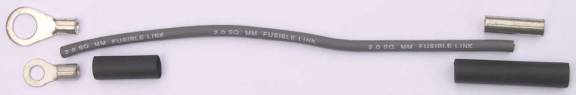  More information on this can be found on THIS WEBSITE I think B or C above would be the most desirable options for keeping an uncluttered look while providing overload protection for the 10 gauge wire circuits. Option A requires nothing to be determined. We are just returning to the stock configuration, only replacing damaged wires with new ones Options B and C require either the amperage rating or the size of the fusible link to be determined. Available fusible links range from 30A to 100A. Fusible link wire is determined by the size of the original wires it is protecting, always being 4 numbers smaller than the wire it is connected to. The 2 white wires we are protecting are 10 gauge, so the proper fusible link wire use would be smaller 14 gauge, or FL-14. This is a gray color, same as the fusible link in our underhood fuse box. Fusible link ratings (wire size) are coded by color. Any final suggestions? This will be my final posting on this topic and I thank everyone here for their concerns and valuable input. .
__________________
. Subaru Ambassador 1996 Polo Green LSi #216..138,100 miles...SOLD JFICX8659TH100216.....Date of Manufacture: November 16, 1995..... Fuji Heavy Industries..Ōta North Plant....Ōta City,. Gunma Prefecture, Japan In-Service Date: January 2, 1997 "The Pristine Green Polo Machine First Polo Green on the Network First Clear front turn signals, JDM Alcyone hood emblem, rear panel, and BOXER engine cover on the Network (US) (2000) First 5000K HID factory fog lights (2007) First SVX JDM BBS wheels on a USDM SVX (2013) HID lighting (5000K) for headlight and H3 fog lights, PIAA SuperExtreme 120W high beams, rebuilt EG33 longblock, Cometic head gaskets, Phase II flexplate, AMR aluminum radiator with custom silicone hoses, 160A high-output alternator in aluminum-ceramic coated case, new design alternator wiring upgrade v.4, rare factory headlight protectors, refinished JDM BBS mesh aluminum wheels and custom, polished billet aluminum new hex center caps, LED grille mod, R1 Concepts high-carbon cryo slotted rotors, Akebono ceramic pads, Goodridge S/S braided brake lines, Smallcar Stage 1 shift kit, ThermalTech aluminum/ceramic-coated valve covers, Energy Suspension urethane front & rear swaybar bushings, Bontrager22 rear swaybar with QS Components Chromoly Teflon/Kevlar endlinks, "$15.00/5 minute" suspension mod. Hella Supertone horns, Custom stainless steel exhaust system with 2" headpipes, Magnaflow cats, AeroTurbine AR25 resonator /AWD "Bullet" muffler. R.I.P. 2010 Subaru Outback Limited 2.5 CVT...338,000 miles. Totaled by a 1,300 lb. COW March 4, 2016  2014 Hyundai Avante Limited ...178,000 miles. Actually quieter and smoother than the Outback  2007 Mazda Miata MX-5 PRHT...102,000 miles. Plenty of parts, service and windshields.  4th Registered Network member 2/21/2001 My NEW locker..I...My Email..I..Wikipedia/SVX . . Last edited by svxcess; 12-04-2018 at 08:59 PM. 
|
|
|


 Threaded Mode