
Live Chat!
SVX or Subaru Links
Old Lockers
Photo Post
How-To Documents
Message Archive
SVX Shop Search
|
SVX Network Forums Live Chat! SVX or Subaru Links Old Lockers Photo Post How-To Documents Message Archive SVX Shop Search |
IRC users: |
|
#46
 05-16-2006, 04:33 PM
|
||||
|
||||
|
Quote:
The measurements should not be taken with the head off. All must be in place and exactly operational as normal. I have advised the correct way to do it. The actual relationship with crankshaft position must be positively varified when all is set up as running. Lift is a separate aspect in the equation. I see that Harvey's instructions have been suggested. In the light of his previous posts, it would be interesting to see those instructions. If decissions are going to be based on measurements made using that which could be suspect, I will have no further confidence in the project. Sincerely, Trevor.
__________________
Trevor, New Zealand. As a child, on cold mornings I gladly stood in cowpats to warm my bare feet, but I detest bull$hit! 
Last edited by Trevor; 05-16-2006 at 04:40 PM. 
|
|
#47
05-16-2006, 06:20 PM
|
||||
|
||||
|
DeltaCam specs
Okay, here you go....
 -Bill (yeah, I really don't have these cams in my engine....honest!)
__________________
Retired NASA Rocket Scientist Most famous NASA "Child" - OSIRIS-REx delivered samples from asteroid BENNU to Earth in Sept. 2023 Center Network Member #989 '92 Fully caged, 5 speed, waiting for its fully built EG33 '92 "Test Mule", 4:44 Auto, JDM 4:44 Rear Diff with Mech LSD, Tuned headers, Full one-off suspension '92(?) Laguna, 6 spd and other stuff (still at OT's place) My Locker
|
|
#48
05-16-2006, 06:23 PM
|
||||
|
||||
|
Harvey's Directions
Trevor,
In response to your request, here's what Harvey PM'ed me: Checking valve timing, and lobe center. This is the method I would use to check the valve timing and find the inlet lobe center. I use a plastic degree wheel stuck, to the harmonic balancer, with double sided tape, with the TDC marks aligned. Set up a wire pointer on one of the bolts on the front of the engine, so that it is in line with the 0 degrees on the degree disc. Zeroing the degree disc to the crank. Set up a dial indicator through the plug hole, and zero it while the piston is at TDC. Rotate the engine( always turning the engine forwards,NEVER TURN IT BACKWARDS) till the dial ind. shows the piston has dropped 0.050". read the degrees the crank has turned pass TDC. Say it is 12*. Turn the engine over till the piston is 0.050" from the TDC. Read the degrees, say it is 8*, that means that the wire pointer is too far to the 12* side, so we half the difference 4*, and move the wire pointer 2* to the 8* side, so that the pointer is aligned with 10* BTDC. This zeros the degree wheel to the crank, it will now read the same 10* at 0.050" before and after TDC. Measuring the valve timing. Set up the dial indicator on the top of the valve follower, zero the needle. There is two different ways to show duration figures, the US way is to start the measurement at 0.050" lift, and end 0.050" from the fully closed position. The other which everyone else uses, is from seat to seat. Turn the engine till the dial shows the first movement, of the valve opening, read off the degrees BTDC. (This is the start of the seat to seat duration.) Keep turning till the follower has moved 0.050", read off the degrees, (this is the start of the US duration). Turn the engine over till the valve is 0.050" from closing, (US closing point), keep turning till the valve has stopped. (end of the s to s duration) The book quotes the timing to be ;Inlet 2* BTDC, 54* ABDC 236* Duration. Exhaust 55* BBDC, 9* ATDC. 244* Duration. Finding the lobe center. Turn the engine till the valve is fully open, zero the dial needle. Turn the engine till the dial shows 0.050" from fully open, read the degrees, keep turning till the valve has closed 0.050", read the degrees. Add the two degree readings together divide by two. This is the inlet lobe center. Worked out from the timing in the book, this is 116* ATDC. If you can find what the factory lobe center is, and what the new cam duration and lobe center is. We will know where we stand. -Bill (aka "Fountain of Cam Knowledge"  ) )
__________________
Retired NASA Rocket Scientist Most famous NASA "Child" - OSIRIS-REx delivered samples from asteroid BENNU to Earth in Sept. 2023 Center Network Member #989 '92 Fully caged, 5 speed, waiting for its fully built EG33 '92 "Test Mule", 4:44 Auto, JDM 4:44 Rear Diff with Mech LSD, Tuned headers, Full one-off suspension '92(?) Laguna, 6 spd and other stuff (still at OT's place) My Locker
|
|
#49
05-16-2006, 09:28 PM
|
||||
|
||||
|
Quote:
__________________
Trevor, New Zealand. As a child, on cold mornings I gladly stood in cowpats to warm my bare feet, but I detest bull$hit!
|
|
#50
05-16-2006, 09:48 PM
|
||||
|
||||
|
Quote:
Thanks, Trevor.
__________________
Trevor, New Zealand. As a child, on cold mornings I gladly stood in cowpats to warm my bare feet, but I detest bull$hit!
|
|
#51
05-17-2006, 05:13 AM
|
||||
|
||||
|
Quote:
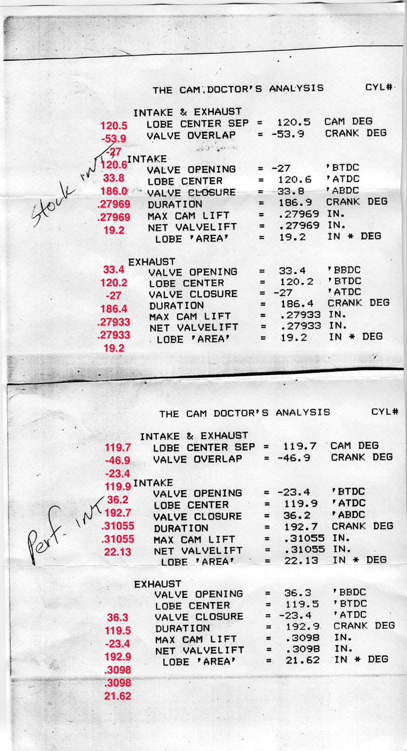
Trevor, The top part of the sheet is supposed to be the specs of the stock intake cams, the bottom the "modified" intake cams. -Bill
__________________
Retired NASA Rocket Scientist Most famous NASA "Child" - OSIRIS-REx delivered samples from asteroid BENNU to Earth in Sept. 2023 Center Network Member #989 '92 Fully caged, 5 speed, waiting for its fully built EG33 '92 "Test Mule", 4:44 Auto, JDM 4:44 Rear Diff with Mech LSD, Tuned headers, Full one-off suspension '92(?) Laguna, 6 spd and other stuff (still at OT's place) My Locker
|
|
#52
05-17-2006, 01:21 PM
|
||||
|
||||
|
Trevor - even more info to tie together!
Trevor,
Could you take a look at this thread to see what you think, relative to how it fits in with the info in this thread? http://www.subaru-svx.net/forum/show...ight=Cam+Lobes -Bill
__________________
Retired NASA Rocket Scientist Most famous NASA "Child" - OSIRIS-REx delivered samples from asteroid BENNU to Earth in Sept. 2023 Center Network Member #989 '92 Fully caged, 5 speed, waiting for its fully built EG33 '92 "Test Mule", 4:44 Auto, JDM 4:44 Rear Diff with Mech LSD, Tuned headers, Full one-off suspension '92(?) Laguna, 6 spd and other stuff (still at OT's place) My Locker
|
|
#53
05-17-2006, 04:42 PM
|
||||
|
||||
|
Quote:
There appears to have been some emphasis towards valve lift, although this may have been so as to be able to accommodate existing cam profiles. There is also reference to reducing valve seat width which will effect seat wear. The SVX has a very large valve area and therefore both of these modifications are not as relevant as they were before the four valve era. Increased valve lift carries with it disadvantages in respect of greatly increased mechanical loading. In both of these areas anticipated improvement must be carefully weighed against the negative effects. My understanding is that you are not intent on building race engines, which will be pulled down and refreshed at short intervals. Based on the limited information you had on hand it would appear that you went with the right lobe shape as a starter, but still have not established where this sits in relation to TDC, which is a VITAL issue. The very essence of valve timing revolves around piston travel and position, relative to valve position and I can not understand how this so far appears have been ignored. I note that Harvey has brought aspects of the inlet tract into the discussion, which does no more than confuse the issue. I agree that this and valve timing are related, but each is independent of the other and with due consideration can be adjusted individually.
__________________
Trevor, New Zealand. As a child, on cold mornings I gladly stood in cowpats to warm my bare feet, but I detest bull$hit!
Last edited by Trevor; 05-17-2006 at 06:24 PM.
|
|
#54
05-17-2006, 10:33 PM
|
||||
|
||||
|
Quote:
Intake opening: -27 BTDC (Very strange figure). Subaru's figure: 2* BTDC (Logical). Intake closing; 33.8 ABDC. Subaru's figure: 54 ABDC. Duration: 186.9 crank degrees. Subauru's figure: (Calculated) 236*. Lobe centre: 120.6* ATDC. Subaru's figure: (Calculated) 120*). N.B. This figure is within tolerance. How can one have confidence in the figures for the modified cams? Your own measurements become even more essential! Cheers, Trevor.
__________________
Trevor, New Zealand. As a child, on cold mornings I gladly stood in cowpats to warm my bare feet, but I detest bull$hit!
|
|
#55
05-18-2006, 03:55 PM
|
||||
|
||||
|
Quote:
This brings up the important point that when profiles as such, are compared one against the other, the associated mechanical arrangements must be taken into account. It is therefore best to use the engine manufactures valve timing figures. All this probably came to mind as a result of early experience. Over Fifty years ago, when I built my first car to go motor racing on a very, very low budget, I studied the effects of valve timing and came up with an idea based on the preceding facts. The engine I was using had a single over head cam operating inclined valves, one each side, via rockers having contact surfaces with a sharp radius. I built these up with hard welding, ground them flat and the result will be obvious. Strangely I have never read of any one else using this cheap but effective method.
__________________
Trevor, New Zealand. As a child, on cold mornings I gladly stood in cowpats to warm my bare feet, but I detest bull$hit!
|
|
#56
05-21-2006, 12:48 AM
|
||||
|
||||
|
After further thought and calculations, it would appear the the figures prefixed with "-" i.e. a negative sign, should be taken as indicating in effect ATDC, not BTDC. If this, as well as point contact measurement is accepted, things fall more or less into place. Please read this in conjuction with my previous posts.
One can of worms, to be sorted out only by means of actual readings in respect of the modified cams. These figures I await with great interest. 
__________________
Trevor, New Zealand. As a child, on cold mornings I gladly stood in cowpats to warm my bare feet, but I detest bull$hit!
Last edited by Trevor; 05-21-2006 at 02:06 AM.
|
|
#57
05-21-2006, 09:45 PM
|
|||
|
|||
|
Timing figures.
The figures quoted in Bills slips are US timing, taken at 0.050" lift as I stated in the PM that I sent him, and has been posted.
Harvey.
__________________
One Arm Bloke. Tell it like it is! 95 Lsi. Bordeaux Pearl, Aust. RHD.149,000Kls Subaru BBS wheels. 97 Liberty GX Auto sedan. 320,000Kls. 04 Liberty 30R Auto Premium. 92.000kls.
|
|
#58
05-21-2006, 11:02 PM
|
||||
|
||||
|
Quote:
I can see why a constant degree of lift was used in the instructions which you provided, so as to elliminate possible error through backlash, but I had presumed that these instructions were specifically intended to establish only the lobe centre. Can you please advise how what you state, can be confirmed as a universal system used in US. This is certainly very important in relation to the exercise underway. It would appear to be a very difficult system to directly convert to that which is normal, considering the variables involved. Can you suggest a conversion factor?
__________________
Trevor, New Zealand. As a child, on cold mornings I gladly stood in cowpats to warm my bare feet, but I detest bull$hit!
|
|
#59
05-22-2006, 12:47 AM
|
|||
|
|||
|
Quote:
2. If you are referring to the way the lobe center is found. It is not to eliminate backlash in the drive train, but the lack of valve movement over the fully open position, that may take more than 15* degrees, we need it more accurate than that. 3. I don't know if it is universal,. but you will have trouble finding a seat to seat measurement in any cam grinders settings. The small ends of the cam opening, don't have a big effect on the results, it is mainly to do with the ramps that open and close the valve. As there are many different types of followers, direct acting flat solid or hydraulic and roller, symmetrical profiles. And the asymmetrical profile for lever finger, rocker types of followers. So they just leave them out and use the business end of the cam, from 0.050" on. Harvey.
__________________
One Arm Bloke. Tell it like it is! 95 Lsi. Bordeaux Pearl, Aust. RHD.149,000Kls Subaru BBS wheels. 97 Liberty GX Auto sedan. 320,000Kls. 04 Liberty 30R Auto Premium. 92.000kls.
|
|
#60
05-22-2006, 04:19 AM
|
||||
|
||||
|
Quote:
P. S. Harvey, there are now accurate answers posted. I appologies for my rather curt message, but I continue to not agree with the logic and some statements in your proposal. What has now been properly set out indicates that my theory although logical was apparently wrong and I accept that yours was basically correct.
__________________
Trevor, New Zealand. As a child, on cold mornings I gladly stood in cowpats to warm my bare feet, but I detest bull$hit!
Last edited by Trevor; 05-22-2006 at 08:26 AM.
|
 |
| Thread Tools | |
| Display Modes | |
|
|


 Linear Mode

