
Live Chat!
SVX or Subaru Links
Old Lockers
Photo Post
How-To Documents
Message Archive
SVX Shop Search
|
SVX Network Forums Live Chat! SVX or Subaru Links Old Lockers Photo Post How-To Documents Message Archive SVX Shop Search |
IRC users: |
|
#16
 11-06-2006, 05:31 PM
|
||||
|
||||
|
Quote:
Your unsolicited (unrequested, not asked for) post has no other purpose other than to instruct. i.e. This constitutes a brief, straightforward, explanatory opening statement of a fact, complimentary to that which was to follow. It would appear that many are unable to decipher good English. I now appears that I have to add that which should have been patently obvious. -------- to instruct, or as is more likely, to obtusely negate posted statements, as they have recently been confirmed as having being made a permanent record. ------------------ DUTY SOLENOID A. A pulse width modulated duty solenoid valve, ( Sometimes known as a pulsoid), as is incorporated in the SVX transmission control system, adjusts pressure in the following manner :- The fluid line is provided with a bleed or bypass via an on/off device in the form of an electrically operated valve. This solenoid valve is opened and closed repeatedly, in a rhythmical manner by a control current which is turned very rapidly on and off by the transmission control unit (TCU). The valve is a normally closed device, and remains closed in the event of the loss off a control current. After passing through this modulated solenoid valve, the continually interrupted pressure is in the form of a pulsed flow. When the peaks level off with the troughs there is a resulting overall steady reduced pressure. The level of this pressure is adjusted by varying the on/off intervals. Most often the length of the on time is adjusted and the number of on/off pulses per second is kept constant. The usual rate is around 50 cycles per second. The resulting adjusted output pressure is therefore delivered as a fluctuating stream. The system incorporates an expansion chamber as a smoothing element, which works as a sort of cushion. This device is usually in the form of a cylinder and piston or diaphragm, backed by a coil spring. In the SVX system the component is described as a Pressure Modifier Accumulator. The high pressure peaks in the stream press the piston outwards and become rounded off, while the low pressure troughs are filled in as a result of the piston moving inwards under spring pressure. The end result is a smoother level of pressure, such that controlled devices are not materially affected. An increase in the volume controlled is achieved by transferring the solenoid regulated pressure to a pressure modifier valve and a regulator valve. It should be clear that by chopping the fluid supply in an adjustable way, pressure control is achieved economically using a simple poppet type solenoid valve, with few mechanical or electrical complications. However the valve remains in a continuos cycling mode, which can impose rather arduous mechanical stresses. THE DROPPING RESISTOR CIRCUIT. It will be immediately apparent that a sudden on off cycle tends to cause what could be called a hammering of the valve seat, even though this is largely checked by the controlled fluid flow. The dropping resistor introduces a second series of current pulses, applied in parallel with the control signal. These shorter pulses are applied during the off cycles and timed to check the travel of the armature as it reaches the closed position, thus reducing both shock and noise. These secondary parallel signals in effect rounds off, the closing period and reduces the closing shock. This arrangement can if required, be made even more sophisticated and configured so as to soften the the opening cycle, as well as the closing of the valve. It will be appreciated that reducing the resistance in the circuit, or opening the circuit by omitting the resistor, has two outcomes. Firstly the relative on time is increased thus increasing the line pressure. Importantly as a second issue, increased shock loads are applied to the valve. SOLENOID C The same principals apply, but the duty is less arduous and therefore no parallel circuit is incorporated. By way of preserving accuracy, I reserve copy rights. ------------------- It should be noted that Harvey claims among other things, that the A solenoid valve is held stationary at variable positions in order to achieve pressure control. Any member in doubt should resort to their ears. Although not loud, the A solenoid does make a noise, which should increase if the resistor circuit is opened. I am unable to confirm this noise myself, as I am partly deaf, but others have mentioned it here in other contexts. (Good one for Harvey to jump on ! ) 
__________________
Trevor, New Zealand. As a child, on cold mornings I gladly stood in cowpats to warm my bare feet, but I detest bull$hit! 
Last edited by Trevor; 11-06-2006 at 10:09 PM. Reason: Typo -- "recorded/record" corrected. 
|
|
#17
11-07-2006, 10:15 PM
|
|||
|
|||
|
BS hunting.
[Quote] Your unsolicited (unrequested, not asked for) post has no other purpose other than to instruct. i.e. This constitutes a brief, straightforward, explanatory opening statement of a fact, complimentary to that which was to follow.
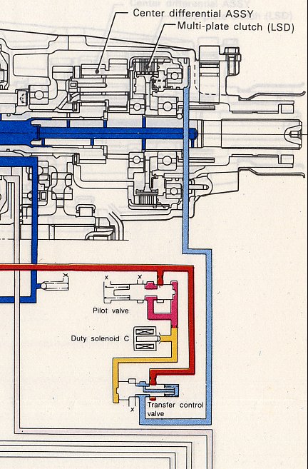
It would appear that many are unable to decipher good English. I now appears that I have to add that which should have been patently obvious. -------- to instruct, or as is more likely, to obtusely negate posted statements, as they have recently been confirmed as having being made a permanent record.[Quote] Well I must admit that there was an ulterior motive for this thread.  It was to bring to the attention of all the readers of this Network, that the Theory that you have infested the forums with, is erroneous, misleading, and a Technical embarrassment to the fine reputation of this Network for supplying helpful, and accurate information. It was to bring to the attention of all the readers of this Network, that the Theory that you have infested the forums with, is erroneous, misleading, and a Technical embarrassment to the fine reputation of this Network for supplying helpful, and accurate information. I am glad that you have supplied it for scrutineering. Though as you say [Quote] By way of preserving accuracy, I reserve copy rights [Quote] I would prefer to investigate the version that you have posted on the Net, rather that your copyrighted, edited version. This is the version that you posted. I have changed some statements to Bold. How the SVX Shift Kit and Duty Solenoid "A" Function Author: Trevor The dubious object of the system is to open the OEM resistor circuit so as to increase transmission line pressure under certain conditions. The object was to insert a pressure sensitive switch in the resistor circuit for this purpose, i.e. the wire cut and the switch inserted. In this situation when the switch operates, the diagnostic fault circuitry will find an open circuit and indicate a fault with a blinking light. In order to prevent this, a high value resistor is connected across the switch contacts, so that the circuit is not fully opened by the switch, but a high resistance inserted in series kills effective operation, as would completely opening the circuit. Take into account the following information which I have posted several times and in particular note reference to the dropping resistor circuit. DUTY SOLENOID VALVE "A"This is a pulse width modulated duty solenoid valve, ( Sometimes known as a pulsoid). The device is incorporated in the SVX transmission control system in order to adjust line pressure in the following manner :- The fluid line is provided with a bleed or bypass via an on/off device, in the form of an electrically operated valve. This solenoid valve is opened and closed repeatedly, in a rhythmical manner by a control current which is turned on and off by the transmission control unit (TCU) at a very fast rate. The valve is a normally closed device, and remains closed in the event of the loss off a control current. After passing through this modulated solenoid valve, the continually interrupted pressure is in the form of a pulsed flow. When the peaks level off with the troughs, there is a resulting overall steady reduced pressure. The level of this pressure is adjusted by varying the on/off intervals. Most often the length of the on time is adjusted and the number of on/off pulses per second is kept constant. The usual rate is around 50 cycles per second. The resulting adjusted output pressure is therefore delivered as a rapidly fluctuating stream. The system incorporates an expansion chamber as a smoothing element, which works as a sort of cushion. This device is usually in the form of a cylinder and piston or diaphragm, backed by a coil spring. In the SVX system the component is described as a Pressure Modifier Accumulator. The high pressure peaks in the stream press the piston outwards and become rounded off, while the low pressure troughs are filled in as a result of the piston moving inwards under spring pressure. The end result is a smoother level of pressure, such that controlled devices are not materially affected. An increase in the volume of fluid controlled, is achieved by transferring the solenoid regulated pressure, to a pressure modifier valve and a regulator valve. It should be clear that by "chopping" the fluid supply in an adjustable way, pressure control is achieved economically using a simple poppet type solenoid valve, with few mechanical or electrical complications. However the valve remains in a continuos cycling mode, which imposes rather arduous mechanical stresses. THE DROPPING RESISTOR CIRCUITIt will be immediately apparent that a sudden on off cycle tends to cause what could be called a hammering of the valve seat, even though this is largely checked by the viscosity of controlled fluid flow. The dropping resistor introduces a second series of current pulses applied in parallel with the control signal. These shorter pulses are applied during the off cycles and timed to check the travel of the armature as it reaches the closed position, thus reducing both shock and noise. These secondary parallel signals in effect, round off the closing period and reduce the closing shock. This arrangement can be made even more sophisticated and configured so as to soften the the opening cycle, as well as the closing of the valve. It will be appreciated that reducing the resistance in the circuit, or opening the circuit by omitting the dropping resistor, has two outcomes. Firstly the relative electrical off time is increased thus increasing the line pressure and therefore makes shifts more abrupt. Importantly as a second issue, increased shock loads are applied to the valve. The resistor should measure between 9 and 15 ohms to be within specifications. The usual is about 12 ohms. It is a documented fact that the line pressure control solenoid is the first to fail due to having by far the most arduous duty to fulfill. Failure is usually mechanical resulting in the valve seat not closing properly and as a result line pressure is markedly reduced. The end results are drastic, especially in respect of transmission friction surfaces. The fault will not necessarily be registered as a fault code, as the armature of the valve can be in the fully closed position with the problem confined to a worn and faulty valve seat. In the event of an electrical fault, which will register, the valve being normally closed, will fail safe and result in maximum line pressure. Dealing with the section titled DUTY SOLENOID VALVE "A" You make a number of statements that you clam as fact. 1. The valve is a normally closed device, and remains closed in the event of the loss off a control current. This is not right. The A Solenoid is a normally open solenoid, as all then other solenoids are. The valve acts as an open drain on the Pilot pressure. The Big picture is here http://www.subaru-svx.net/photos/files/oab_au/39645.jpg But this is a simpler diagram from the WSM, that I have coloured the pressures the same as the main picture.  The dark red Line pressure, is reduced to a low Pilot pressure (red) by the Pilot valve, on the right. This pressure is applied to the top and bottom of the Pressure Modifier Valve. The Pilot pressure flows through a restriction to the bottom of the PM valve, and the A Solenoid. As it is an open drain, the Pilot pressure below the restriction (yellow) is reduced, so the valve is pushed down against its spring, by the pressure on the top to open the valve. This allows the Pilot pressure to flow to the Pressure Regulator Valve, to add to the spring pressure exerted on the valve. This is the state the components are in when the Line pressure is in a normal high Line pressure condition. If we close the A Solenoid, the drain on the pilot pressure below the restriction will stop, and the pressure on the bottom of the PM valve will rise to the same as the top of the valve. With the pressures equalised the spring will be able to push the valve up, to close off the flow of Pilot pressure to the Regulator valve. With the added Modified Pressure assisting the Regulator spring removed, the Line pressure is reduced. Any variation in the flow of the A solenoid, will vary the Line pressure by the same rate. The problem with the article, starts with the way the A solenoid controls the flow, inline with the Duty Cycle signal from the TCU. I maintain that the A solenoid valve opening is adjusted to any position the Percentage of Duty Cycle signalled by the TCU. The resultant output pressure is smooth and varied. Trevor maintains that the A solenoid is opened and closed 50 times a second, the open time varies with the Duty cycle pulse width. The resultant output pressure is therefore delivered as a rapidly fluctuating stream, that is smoothed out by the Pressure Modifier Accumulator. If we look at the diagram, if the solenoid opens and closes 50 times a second, the Pressure Modifier valve must also move at the same rate, as the Pressure Modifier Accumulator is on the other side of this valve. If we look at the Big Picture we find that this same yellow solenoid pressure, that is going up and down at 50 Hz. is also feed to the Accumulator Modifier Valve. This valve adjusts the pressure that is applied to the back of the gear shift Accumulators to soften the change, in line with Throttle pressure, so these will also move at the same 50Hz rate. As the Pulse Width on time for this to happen, reduces from 95% to 5% these valves would have to be able to turn on and off in 2 Microseconds. Even at a 50% Duty cycle, the valve would have to open and close in 20 milliseconds.  2. Trevor states. [Quote] The resulting adjusted output pressure is therefore delivered as a rapidly fluctuating stream. The system incorporates an expansion chamber as a smoothing element, which works as a sort of cushion. This device is usually in the form of a cylinder and piston or diaphragm, backed by a coil spring. In the SVX system the component is described as a Pressure Modifier Accumulator. The high pressure peaks in the stream press the piston outwards and become rounded off, while the low pressure troughs are filled in as a result of the piston moving inwards under spring pressure. The end result is a smoother level of pressure, such that controlled devices are not materially affected.[Quote]. This is not the function of this accumulator. As the Pressure Regulator Valve uses a spring to regulate the Line pressure, the regulators spool can move up or down to account for the pressure changes, in Line pressure, due to clutch or servo operation. When the modified pressure is added to the spring pressure, it is no longer free to respond to fast Line pressure fluctuations because of the incompressible oil. To allow the valve to respond under these conditions, the accumulator is included in this Modified pressure line, this allows the oil to be forced from the Regulator spring area, when the Regulator valve has to move quickly to maintain regulated pressure. I think it is fairly obvious by now that the theory that this A Solenoid opens and closes at 50Hz in the 4EAT is simplistic and just not possibly. To state that the chopped pressure is smoothed by the accumulator such that controlled devices are not materially affected is an embarrassment to see on our Technical forums. The Dropping Resistor section is tailored in an attempt to iron out the problems in the erroneous 50Hz open/closing theory. The electrical circuit operation is as I have stated in the first post on this thread, so I wont repeat it. Trevors statement, [Quote] It is a documented fact that the line pressure control solenoid is the first to fail due to having by far the most arduous duty to fulfill. Failure is usually mechanical resulting in the valve seat not closing properly and as a result line pressure is markedly reduced. The end results are drastic, especially in respect of transmission friction surfaces. The fault will not necessarily be registered as a fault code, as the armature of the valve can be in the fully closed position with the problem confined to a worn and faulty valve seat. In the event of an electrical fault, which will register, the valve being normally closed, will fail safe and result in maximum line pressure. [Quote] As the A solenoid is a fully open drain for full Line pressure, the condition of the valve seat, cant reduce the Line pressure at all. It would only affect the lowest Line pressure that it can be set to, so the whole statement is false. Trevor completely ignores the fact that the B and C solenoids operate under the same conditions as the A solenoid. Yet he makes no mention of them needing an accumulator, or that they need a second parallel signal, to prevent seat damage. ") This is because the A solenoid operates the same as the B, and C Solenoids. This is because the A solenoid operates the same as the B, and C Solenoids. The posts that you have posted, and the article, are misleading and utterly wrong. I would suggest that to uphold the integrity, of the Subaru-SVX. Net, that you either correct them, or do the right thing by the Forum, and delete them. Harvey.
__________________
One Arm Bloke. Tell it like it is! 95 Lsi. Bordeaux Pearl, Aust. RHD.149,000Kls Subaru BBS wheels. 97 Liberty GX Auto sedan. 320,000Kls. 04 Liberty 30R Auto Premium. 92.000kls.
|
|
#18
11-08-2006, 05:39 AM
|
||||
|
||||
|
Harvey,
Your sarcastic demeanor is apparent and noted. In an effort to discredit me you have tried to infer that I have put forward two sets of facts. That included in this thread was the original presented in a thread on the same subject some time ago, whereas the second version has been edited by way of clarity. The original was presented here specifically so that you can not accuse me of any modification to my original statement. Either way the principal described remains exact and intact without variation. Your attempt to cause doubts is stupid. I will answer the individual points you make against what I have set down, in my own time. The many previously unanswered questions I have put to you previously, relating the same issue will at the same time be aired. You will no doubt be assuming that as in the past, the current issue will become drawn out to the extent that members will become completely confused and loose interest, before proper conclusion is reached. In order to prevent a repetition of your well exercised ploy, I simplify the argument to one vital, exclusive fact. All reading this should/will understand that the proposal you present depends on but one fact; i.e. that the SVX A solenoid valve is held stationary at variable positions in order to achieve pressure control and that this is achieved via an electrical signal. You have now stated this as being a fact many times and there can be no withdrawal or excuse, e.g. "As usual I didnt explain it very well . I open my case by stating that this proposed operation of SVX solenoid A, within its normal environment, as described by Harvey, is impossible. It is up to you Harvey to scientifically prove and demonstrate how this is/can be achieved, in which case you will posses a novel principle which will support a world patent of immense value. I have practical hands on experience in the area of registered designs and patents. I can confirm that I and many others will be happy to subscribe towards setting up a Company to exploit your property and you can be assured of huge capital gain. I admit to a retaliation in respect of sarcasm, but the words constitute viable fact. Trevor. *<)
__________________
Trevor, New Zealand. As a child, on cold mornings I gladly stood in cowpats to warm my bare feet, but I detest bull$hit!
|
|
#19
11-09-2006, 09:10 PM
|
||||
|
||||
|
Errors !
Rather than traipse through all of Harveys errors in his tirade against me, I draw attention to the the most blatant. The first of note being, typo accepted, ------
Harvey States ---This is not right. The A Solenoid is a normally open solenoid, as all then other solenoids are. The valve acts as an open drain on the Pilot pressure. ( N.B. as all the solenoids are.) Trevor requests ------ Please those with a 1992 Service Manual, refer to the excellent fluid schematics in Section 3. These schematics clearly and positively illustrate solenoid valves 1,2 and 3 as shut and not passing fluid when off. (Normally Closed) and open when on. (Energised from the normally closed position.) It should also be noted that all solenoids including A and C. are depicted within the schematics in exactly the same style and I agree with Harvey that all are of similar configuration. However all are NORMALLY CLOSED. Harvey, the requirement for a withdrawal and apology is leaning your way a little. 
__________________
Trevor, New Zealand. As a child, on cold mornings I gladly stood in cowpats to warm my bare feet, but I detest bull$hit!
|
|
#20
11-11-2006, 06:01 PM
|
||||||||
|
||||||||
|
Quote:
Oh Trev, what can I say????????  Its not often you are right,,,,,,,,,,,,,,,,,,,but you are wrong again. Its not often you are right,,,,,,,,,,,,,,,,,,,but you are wrong again. The problem is that you are reading the Work Shop Manuals, and trying to work out how it all works. The Manuals are written for Automotive Technicians, Mechanics, or Engineers to use for diagnosing, rebuilding and resetting to specifications. The Book doesnt tell you how it works, it assumes the reader has the necessary level of Automotive knowledge on the operation of Auto Transmissions. The No.1, 2 and 3, shift solenoids that you are referring to, are operated by a DC current. They are either switched on or off, they are not operated by a Modulated Duty Cycle, as the A, B, and C solenoids are. They are all a normally open drain on a Pilot pressure. The wording on the Hydraulic circuit diagram that you are looking at, depicts the electrical state of the shift solenoids, not the hydraulic state. This is the Diagram, depicting the valves in the Neutral/Park condition.  If you expand the Pict. You can see that these solenoids operate off the same Pilot pressure as the A solenoid. They have the same type of restrictions in the Pilot line, just before the solenoids. In the diagram shift solenoids 1, and 2, are both turned on electrically, to shut off the drain on the Pilot pressure, so that the Pilot pressure to the bottom of the shift spool valves is raised to push the spools up. The No. 3 solenoid is turned off electrically, so the drain on the Pilot pressure is still open, the pressure on the solenoid side of the restriction, is drained off through the open solenoid. The Hydraulic circuit that the Auto uses is like no other hydraulic system that you would be used to. Systems like the Power steering or Brake system are a sealed, static pressure system, no leaks. The Auto system is a mass of leaks, oil pressure seeps out of every pipe, clutch and servo. This is intentional as the oil leaking through the open drains and leaks, keep the oil continually circulating to cool and lube the box. The pump has more that enough volume to maintain the necessary pressure, regardless of the leaks. Quote:
Quote:
2. Trevor states. Quote:
Quote:
 that it too has a restriction in the Pilot pressure line just before the C solenoid, the open solenoid drains the pressure off, and the spring pressure closes the transfer valve to turn then clutch off. When the Solenoid is turned on by the Duty Cycle current, it reduces its drain, to allow the Pilot pressure to rise to open the transfer valve and send Line Pressure to the transfer clutch. This C solenoid circuit operates the transfer clutch, with a smoothly varying pressure, without a pulsation smoothing accumulator, or a supporting dropping resistor circuit, to do as you clam. You have not supported the two clams that you have made in posts on this site or on the Web. Namely that, 1. The valves are normally closed, and the associated statement that Quote:
Quote:
Quote:
Harvey.
__________________
One Arm Bloke. Tell it like it is! 95 Lsi. Bordeaux Pearl, Aust. RHD.149,000Kls Subaru BBS wheels. 97 Liberty GX Auto sedan. 320,000Kls. 04 Liberty 30R Auto Premium. 92.000kls.
|
|
#21
11-12-2006, 11:11 PM
|
||||
|
||||
|
B.s.
Harvey,
As of old, by averting members attention towards an endless barrage of nonsense and related images, you continue your efforts to hide the real issue. I will stick to facts and again disclose that you are again and again wrong. With facts in mind, I took a drive this morning in my new toy, a Mazda MX 5 Miata. As I have said before, the SVX is an old mans Grand Touring Car in my book and not my cup of tea on the fun front. Out in the open air again, driving something a little more frisky, I called on transmission specialists who are used here by Subaru dealers, and as a result are well versed in the E-4AT system. My object was to obtain a further back up opinion, in respect of what I had already learned from others and had also analysed myself. The discussion was interesting and informative. Each and every statement I have made regarding the operation of solenoid A and C in the 4 EAT transmission was confirmed as exactly correct. A set of solenoids, moments before taken from a transmission being overhauled, was thrust at me with the comment, cut it open and see for yourself. Detailed manuals were also produced as further proof of the pudding. Nice guys. The components of the solenoid valves are housed within shells well and truly swaged as one piece, so that some arduous grinding was required to explore their inner secrets. But first the A solenoid was pressurised, both de-energised and energised. The taste was bad, but the confirmation that the valve is indeed NORMALLY CLOSED was rewarding, even though not unexpected. The first item of interest was a quite strong spring, which clearly holds the valve shut/closed against a seat, when NOT ENERGISED. There was also evidence of a probable pre-set adjuster for the spring, used during manufacture but otherwise fixed solid. Second of interest was the very short available travel, (approx. 2 m.m. max.) and the fact that as anticipated the design constitutes a purely on off device, pulled open by means of a solenoid. There is absolutely no possibility of partial opening/closing as claimed by Harvey, even if this were electrically possible, which it is not. The weird concept, for so long and so often stated by Harvey, is confirmed both impossible and stupid. Furthermore, without my prompting, it was pointed out to me that the usual items which follow a pulse width modulated solenoid valve, will not be affected by any possible ripple in the line pressure, because of their inherent reciprocating weight/mass, even if the smoothing provided was ineffective. A compressed high frequency fifty cycle ripple, is far from a tidal wave. In point of fact it would appear that I have drawn too much attention to the aspect of smoothing. Also mentioned by the experts, was that some minor details vary between manufacturers in respect of the same component, but the principal of operation is always the same and therefore the samples provided were exactly indicative. The dropping resistor circuit was discussed and it was agreed that I had explained this aspect correctly and in greater detail than the instruction manuals, which simply outline the basics. Harveys anticipated next move will probably be to state that his knowledge far exceeds that of all others. Or he will he accuse me of being a liar in respect of the information I have received. His problem is that like me, members can easily obtain and dissemble an A solenoid for inspection, should they be in any doubt. Whatever, I am sure that Harvey will have been in the interim rejoicing in anticipation of again posting more derogatory, haughty, sarcastic, comments from his ivory tower, or glass house, but not his current deep hole. Having dug even deeper he must now climb out of it. Myself, I leave my statements presently under criticism intact, but possibly subject to expansion at a later date. When the dust settles to put it nicely, there has been some ****e pushed up hill here, I will also comment regarding other useful evidence I have uncovered in respect of solenoid failure leading to transmission disaster. Again ****e is involved.
__________________
Trevor, New Zealand. As a child, on cold mornings I gladly stood in cowpats to warm my bare feet, but I detest bull$hit!
|
|
#22
11-15-2006, 10:09 PM
|
||||||
|
||||||
|
Quote:
Still nothing to support your now dubious claims. This bit is hilarious,  Quote:
Well I have done my best to explain from the WSM how the A solenoid works, if you can explain how the line pressure will work with a normally closed solenoid, go to it, you can use my diagrams from the WSM. All this crap you go on with, comes down to the fact that you can not conceive that the A, B,C, solenoids in the gear box, the Power steering solenoid, the Idle Air Control solenoid, the Carbon canister Purge solenoid, Exhaust Recirculation valves solenoid, the Air Con Actuator solenoid, are all driven by a Pulse Width Modulated signal to be smoothly moved, to any position, and held there by the Duty Cycle signal. If you can't understand how these operate, you have no chance of understanding how Subarus new 'Drive by wire' throttle actuator operates. As it also uses a Pulse Width Modulated rotary actuator, to smoothly open the throttle to any position, and hold it there, with an accuracy of 1 deg at low openings and 5 degrees across the rest of the opening range. I would suggest that you read up on this way of operating Electromagnetic solenoids. This is some resource for you to read. Quote:
Quote:
Quote:
http://www.theleeco.com/EFSWEB2.NSF/...e!OpenDocument Quote:
I again ask you to correct, or delete the unsupported claims you have made in posts on this Net. Harvey.
__________________
One Arm Bloke. Tell it like it is! 95 Lsi. Bordeaux Pearl, Aust. RHD.149,000Kls Subaru BBS wheels. 97 Liberty GX Auto sedan. 320,000Kls. 04 Liberty 30R Auto Premium. 92.000kls.
|
|
#23
11-16-2006, 01:33 AM
|
||||
|
||||
|
As I posted in anticipation, you have stated with your usual sarcasm, that you know more than the experts.
Your problem is that you have now exactly indicated that you are completely baffled in respect of the operation of different types of solenoid. More so from what you indicate you have read. That contained in the SVX transmission is a simple on/of device as anyone can verify by simple inspection. Linear and proportioning solenoid valves as well as rotary actuators are a different species. As I have several times pointed out to you these utilise, a feed back loop. Read again your text books and learn. Others who have the ability to assimilate fact will understand my summary as follows:- Common sense dictates that it is impossible to retain a free variable, existing within a changing environment, in a fixed state by means of pre-set control parameters. Consider the impossibility of a balancing act without the feedback of sight and feel, to provide the means of continual correction in respect of the forces involved. In order to utilise an electric solenoid to maintain a set point, this problem is overcome by incorporating a feed back loop, such that the controlling force can be continuously adjusted by way of compensation to counter variable external forces or variations in mechanical resistance. N.B. In respect of a simple on/of solenoid valve, as used in the SVX transmission, the requirements are impossible to achieve due to the very short movement of the armature and the poppet valve configuration. However in the case of a linear solenoid, there is sufficient armature travel to allow practical measurement. The operating current can be monitored by means of sophisticated circuitry, so as to provide feedback, detected as a result of the magnetic field varying and therefore operating current changing, in line with armature position. The control current can then be continuously adjusted to compensate against variable extraneous forces. When the application involves a proportioning solenoid valve, a secondary coil is often employed for use in establishing a feedback signal. These valves involve relatively long solenoid movement, which greatly assists in resolving a signal. As an alternative, downstream pressure can be monitored in order to establish the required feed back loop. This is the method used in most industrial control application.
__________________
Trevor, New Zealand. As a child, on cold mornings I gladly stood in cowpats to warm my bare feet, but I detest bull$hit!
|
|
#24
11-17-2006, 03:03 AM
|
||||
|
||||
|
Harvey,
Set out below is text copied exactly from the third site that you have suggested in your last post by way of anecdotal evidence. Evidence it most certainly is and all should read it carefully. I am sure that others will accurately understand the text, but for you I decipher. Your quoted article ---------- Problem: How can a valve which is inherently bi-stable be cycled to control average flow? [Bi stable:- From Funk and Wagnalls standard dictionary, Bi -- twice, double, two. Stable -- standing firmly in one place. i.e. A valve which is confined to two fixed positions and is therefore confined to on/off operation, with no possible intermediate positions.] [Cycled:- F & W std dcnr. To pass through cycles. See also cycle, below.] Solution: Pulse width modulation (PWM) can be used to control average flow by varying the valve duty cycle on some (usually) fixed base frequency to match the flow requirement. [Pulse width modulation (PWM) :- The varying of on/off times within an on/off electrical control signal, usually operating at a fixed frequency.] [Cycle :- F & W std dcnr. A recurring period within which certain events or phenomena occur in a definite sequence.} [Frequency :- F & W std dcnr. The number of times something occurs within a particular extent of time.] For example, if a valve can flow 3.0 liters per minute in the full on state, then the valve is cycled so that it is ON for 33% of the time, the valve will flow approximately 33% of the total flow capacity, or about 1 liter per minute. [N.B. --- cycled ON for 33% of the time. (Therefore the valve is OFF for 67% of the time)] By controlling the pressure and system constraints and characterizing the dynamic performance, a very reliable means of controlling flow can be obtained. With the PWM method, flow can be easily controlled in a range exceeding 10:1, up to a possible 40:1. This ratio of maximum total flow to minimum total flow is sometimes called the "turn-down ratio" of a valve or system. For example, if flow can be controlled between 0.3 and 3.0 liters per minute, then the turn-down ratio is 10:1. More or less resolution can be obtained by altering pressure and frequency, or by changing valve dynamics. [N.B. By altering pressure and FREQUENCY. See above. i.e. the rate per second of the on/off movements.] Harvey you have put forward this article on the basis that it proves your theory that a simple on/off solenoid valve, as used for pressure control within the SVX transmission, is held stationery part open/closed as a means of controlling pressure. Those who have read the text will see that it in fact proves you wrong, and by contrast that my explanation is exactly correct. This thread, to which you claim title, brings to mind days gone by when cycle racing was my sport. There was a competitor, who by deed of his demeanour, earned the nick name, MAD HARVEY".
__________________
Trevor, New Zealand. As a child, on cold mornings I gladly stood in cowpats to warm my bare feet, but I detest bull$hit!
|
|
#25
11-17-2006, 09:56 PM
|
||||
|
||||
|
I love these debates - I just wish I were smart enough to understand them
Harry
__________________
newsvx 1992 SVX LSL, #1215 1997 SVX LSi, #370 "I live with fear every day. Sometimes she lets me go racing." "Getting Older and Slower" Locker: http://www.subaru-svx.net/photos/user.php?newsvx
|
|
#26
11-18-2006, 02:39 PM
|
||||
|
||||
|
I have one question. Well, for now anyway.
If it's agreed that duty solenoids A, B and C operate in the same manner, then I submit a photo of C as a model. It appears to be closed. Since it's not energized, wouldn't it be considered in it's "normal' state?
|
|
#27
11-18-2006, 03:14 PM
|
|||
|
|||
|
QUOTE=elninoalex]I have one question. Well, for now anyway.
If it's agreed that duty solenoids A, B and C operate in the same manner, then I submit a photo of C as a model. It appears to be closed. Since it's not energized, wouldn't it be considered in it's "normal' state?[/QUOTE] OK mate. What makes you believe it is closed? Is it because the check ball is held on the seat by the return spring? This is the C solenoid opened up:  When it is not electrically on, the valve is hydraulically open. When the valve has the pilot pressure applied to it, it pushes the check ball back against the armature, and the pilot pressure flows through the valve. When the Duty cycle Pulse is increased, the magnetic push on the armature, applies pressure to the ball to push it into the seat area to restrict the oil flow. These hydraulic solenoids use the check valve to close the valve when the engine is stopped to prevent the valve body from draining the oil out of the passages, but when the box is running the check ball is pushed open by the pilot flow. Is that what you mean? Harvey.
__________________
One Arm Bloke. Tell it like it is! 95 Lsi. Bordeaux Pearl, Aust. RHD.149,000Kls Subaru BBS wheels. 97 Liberty GX Auto sedan. 320,000Kls. 04 Liberty 30R Auto Premium. 92.000kls.
|
|
#28
11-18-2006, 04:09 PM
|
||||
|
||||
|
Quote:
This is the C solenoid opened up: When it is not electrically on, the valve is hydraulically open. When the valve has the pilot pressure applied to it, it pushes the check ball back against the armature, and the pilot pressure flows through the valve. When the Duty cycle Pulse is increased, the magnetic push on the armature, applies pressure to the ball to push it into the seat area to restrict the oil flow. These hydraulic solenoids use the check valve to close the valve when the engine is stopped to prevent the valve body from draining the oil out of the passages, but when the box is running the check ball is pushed open by the pilot flow. Is that what you mean? Harvey. [/QUOTE]Thanks Harvey, it's much easier to visualize by seeing the internals. So what's considered 'normal' position would be when it has pilot pressure but is not electronically energized?
|
|
#29
11-18-2006, 04:22 PM
|
|||
|
|||
|
Quote:
Well not quite exactly. You left out the main point.This bit Quote:
 The operative words here are, decreasing NORMALLY OPEN PORT FLOW over time, As you can see the valve with zero PWM applied, flows 3.25 Lt/min, when the PWM is increased to 50%, the flow through the valve has decreased to 1.5 Lt/min, at 97% PWM, the valve has closed to decrease the ATF flow to zero. The page is here;http://www.theleeco.com/EFSWEB2.NSF/...e!OpenDocument Harvey.
__________________
One Arm Bloke. Tell it like it is! 95 Lsi. Bordeaux Pearl, Aust. RHD.149,000Kls Subaru BBS wheels. 97 Liberty GX Auto sedan. 320,000Kls. 04 Liberty 30R Auto Premium. 92.000kls.
|
|
#30
11-18-2006, 04:27 PM
|
|||
|
|||
|
Quote:
Yes that is right, full pilot flow, no electrical signal. Harvey.
__________________
One Arm Bloke. Tell it like it is! 95 Lsi. Bordeaux Pearl, Aust. RHD.149,000Kls Subaru BBS wheels. 97 Liberty GX Auto sedan. 320,000Kls. 04 Liberty 30R Auto Premium. 92.000kls.
|
 |
| Thread Tools | |
| Display Modes | |
|
|


 Linear Mode

