A member here recently sent me an email asking this question
Quote:
|
How would one recalibrate the tcm on an svx to change the line pressure of the transmission.
|
As we know, the line pressure is controlled by Duty Solenoid A, so I'm rephasing the question as "How can we adjust the duty cycle of solenoid A?".
The subroutine that determines the Sol A Duty cycle is at address EBAA in the USDM TCU (rom id:705404). First it chooses a map from a list of thirty seven 16bit map addresses at location C870.
Code:
0000C870   C9 0E C9 26 C9 3E C9 56 C9 0E C9 0E C9 6E C9 86
0000C880   C9 B6 C9 CE C9 0E C9 9E C9 E6 C9 FE CA 16 C9 0E
0000C890   CA 2E CA 46 CA 5E CA 76 CA 8E CA A6 CA BE CA D6
0000C8A0   CA EE CA A6 CA A6 CB 06 CB 1E CB 4E CB 66 CA A6
0000C8B0   CB 36 CB 7E CB 96 CB AE CA A6
The first block of 16 addresses (C90E,C926,C93E,....,CA16,C90E) are used when the Torque Control Signal has failed (trouble code 25).
The next address CA2E (at C890) is used for Reverse gear.
The next four addresses (CA46,CA5E,CA76,CA8E), I'm not quite sure about. Maybe they are used under some kind of error condition. The 1st one related to 1st gear, the 2nd for 2nd gear etc.
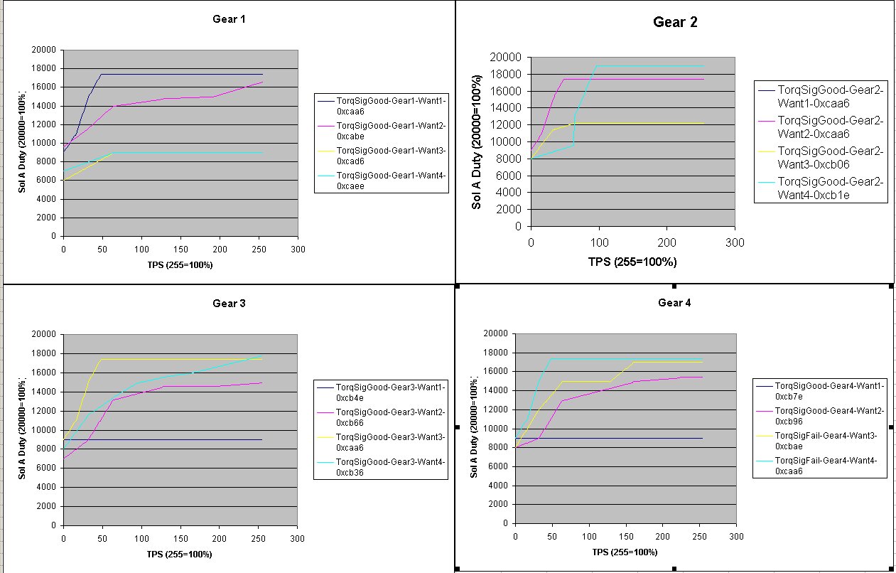
The important part is the final block of 16 addresses from C89A to C8B9. These are split as follows
Code:
        Want_1  Want_2 Want_3 Want_4
Gear_1   CAA6   CABE   CAD6   CAEE
Gear_2   CAA6   CAA6   CB06   CB1E
Gear_3   CB4E   CB66   CAA6   CB36
Gear_4   CB7E   CB96   CBAE   CAA6
To explain, if the car is driving along happily in 3rd, it will use Gear_3_Want_3, the map at CAA6. If it is in 3rd, but has decided that it is about to change down to 2nd, it will use Gear_3_Want_2, the map at CB66. Similarly if it is in 3rd but has decided that it is about to change up to 4th then it will use Gear_3_Want_4, the map at CB36.
Now I'll explain how to decode the maps, taking the one at CAA6 as an example:
Code:
0000CAA0   xx xx xx xx xx xx 0F 7D 23 28 1F FA 1B 58 2F 96
0000CAB0   27 D8 5F 00 43 F8 FF 00 43 F8 xx xx xx xx xx xx
Split the data into groups of 4 bytes and arrange as follows:
Code:
TPS  M  C
0F   7D 2328
1F   FA 1B58
2F   96 27D8
5F   00 43F8
FF   00 43F8
Converting these from Hex into Decimal, we get:
Code:
TPS   M   C
15    125  9000
31    250  7000
47    150 10200
95      0 17400
255     0 17400
The first column is a TPS value from 0 to 255. 255 represents 100% throttle. The table means: "If the TPS value is up to 15, let M=125 and C=9000. If the TPS value is between 16 and 31, let M=250 and C=7000. etc)
Now we use the straight line formula y=mx+c. For example, if we have 10% throttle, that's a TPS value of 25, so we select the 2nd line of the table, M=250 and C=7000. Now we do y = (250*25)+7000 = 13250.
The duty cycles in the TCU are represented by numbers from 0 to 20000. So 13250 is about 66% duty.
I've plotted some graphs to show the different maps.
That's how the base Sol A duty cycle is calculated. Using the information above, you should be able to recalibrate the line pressure. But there is a little bit more to it. After calculating the base duty cycle, it applies a compensation based on the atmospheric pressure signal. It compares the barometric pressure to a list of 8 thresholds at address CBC6 and chooses the corresponding map address from a list of C8BA.
Code:
0000C8B0   xx xx xx xx xx xx xx xx xx xx CB CE CB E6 CB FE
0000C8C0   CC 16 CC 2E CC 46 CC 5E CC 76 xx xx xx xx xx xx
To illustrate how the adjustment maps are encoded, I'll decode the one at CBCE:
Code:
TPS  X  Y  Z
20   00 08 80
40   20 0C 82
60   40 0C 85
80   60 10 88
A0   80 08 8C
FF   A0 00 8E
For TPS values up to 20 (hex) use row 1, for TPS values up to 40 (hex) use row 2 etc. Formula is something like y=(((TPS-X)*2Y+Z)/100-80)*64. All values in hex. This gets added onto the base duty cycle. If you really want to mess with the atmospheric pressure compension, then I suggest you study the code between EC86 and ECD6 and check that I've got the formula right as I'm not entirely sure of it. But I don't really see any need to adjust these compensation maps - the base map is the one you want to play with.
If the vehicle is not fitted with a barometic pressure sensor, or the sensor is faulty then the compensation is calculated differently based on current gear and vehicle speed. I haven't fully analysed it because it should not happen in the normal case.
I hope that information is helpful. I should also add that the first block of 16 maps at C870, the ones that are used if the torque control signal fails, are decoded in exactly the same way as the normal case ones at C89A.
I have not looked at the non-USDM code. The VTD boxes may work differently.