Quote:
|
Originally Posted by Trevor
Rather than traipse through all of Harveys errors in his tirade against me, I draw attention to the the most blatant. The first of note being, typo accepted, ------
Harvey States ---This is not right. The A Solenoid is a normally open solenoid, as all then other solenoids are. The valve acts as an open drain on the Pilot pressure.
( N.B. as all the solenoids are.)
Trevor requests ------ Please those with a 1992 Service Manual, refer to the excellent fluid schematics in Section 3. These schematics clearly and positively illustrate solenoid valves 1,2 and 3 as shut and not passing fluid when off. (Normally Closed) and open when on. (Energised from the normally closed position.)
It should also be noted that all solenoids including A and C. are depicted within the schematics in exactly the same style and I agree with Harvey that all are of similar configuration. However all are NORMALLY CLOSED.
Harvey, the requirement for a withdrawal and apology is leaning your way a little.   |
Oh Trev, what can I say????????

Its not often you are right,,,,,,,,,,,,,,,,,,,but you are wrong again.
The problem is that you are reading the Work Shop Manuals, and trying to work out how it all works. The Manuals are written for Automotive Technicians, Mechanics, or Engineers to use for diagnosing, rebuilding and resetting to specifications. The Book doesnt tell you how it works, it assumes the reader has the necessary level of Automotive knowledge on the operation of Auto Transmissions.
The No.1, 2 and 3, shift solenoids that you are referring to, are operated by a DC current. They are either switched on or off, they are not operated by a Modulated Duty Cycle, as the A, B, and C solenoids are. They are all a normally open drain on a Pilot pressure. The wording on the Hydraulic circuit diagram that you are looking at, depicts the electrical state of the shift solenoids, not the hydraulic state. This is the Diagram, depicting the valves in the Neutral/Park condition.

If you expand the Pict. You can see that these solenoids operate off the same Pilot pressure as the A solenoid. They have the same type of restrictions in the Pilot line, just before the solenoids. In the diagram shift solenoids 1, and 2, are both turned on electrically, to shut off the drain on the Pilot pressure, so that the Pilot pressure to the bottom of the shift spool valves is raised to push the spools up. The No. 3 solenoid is turned off electrically, so the drain on the Pilot pressure is still open, the pressure on the solenoid side of the restriction, is drained off through the open solenoid.
The Hydraulic circuit that the Auto uses is like no other hydraulic system that you would be used to. Systems like the Power steering or Brake system are a sealed, static pressure system, no leaks. The Auto system is a mass of leaks, oil pressure seeps out of every pipe, clutch and servo. This is intentional as the oil leaking through the open drains and leaks, keep the oil continually circulating to cool and lube the box. The pump has more that enough volume to maintain the necessary pressure, regardless of the leaks.
Quote:
|
It should also be noted that all solenoids including A and C. are depicted within the schematics in exactly the same style and I agree with Harvey that all are of similar configuration. However all are NORMALLY CLOSED.
|
If you agree that
Quote:
|
that all solenoids including A and C. are depicted within the schematics in exactly the same style and I agree with Harvey that all are of similar configuration
|
. Then you can not still maintain these statements;
2. Trevor states.
Quote:
|
The resulting adjusted output pressure is therefore delivered as a rapidly fluctuating stream. The system incorporates an expansion chamber as a smoothing element, which works as a sort of cushion. This device is usually in the form of a cylinder and piston or diaphragm, backed by a coil spring. In the SVX system the component is described as a Pressure Modifier Accumulator. The high pressure peaks in the stream press the piston outwards and become rounded off, while the low pressure troughs are filled in as a result of the piston moving inwards under spring pressure. The end result is a smoother level of pressure, such that controlled devices are not materially affected.
|
Quote:
|
THE DROPPING RESISTOR CIRCUITIt will be immediately apparent that a sudden on off cycle tends to cause what could be called a hammering of the valve seat, even though this is largely checked by the viscosity of controlled fluid flow. The dropping resistor introduces a second series of current pulses applied in parallel with the control signal. These shorter pulses are applied during the off cycles and timed to check the travel of the armature as it reaches the closed position, thus reducing both shock and noise. These secondary parallel signals in effect, round off the closing period and reduce the closing shock. This arrangement can be made even more sophisticated and configured so as to soften the the opening cycle, as well as the closing of the valve."
|
As we can see from the C Solenoid diagram,
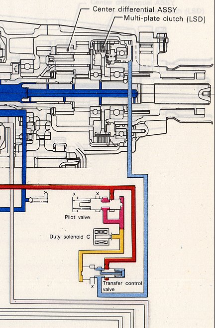
that it too has a restriction in the Pilot pressure line just before the C solenoid, the open solenoid drains the pressure off, and the spring pressure closes the transfer valve to turn then clutch off. When the Solenoid is turned on by the Duty Cycle current, it reduces its drain, to allow the Pilot pressure to rise to open the transfer valve and send Line Pressure to the transfer clutch.
This C solenoid circuit operates the transfer clutch, with a smoothly varying pressure, without a pulsation smoothing accumulator, or a supporting dropping resistor circuit, to do as you clam.
You have not supported the two clams that you have made in posts on this site or on the Web. Namely that,
1. The valves are normally closed, and the associated statement that
Quote:
|
the valve seat not closing properly and as a result line pressure is markedly reduced. The end results are drastic, especially in respect of transmission friction surfaces."
|
2. That
Quote:
|
This solenoid valve is opened and closed repeatedly, in a rhythmical manner by a control current which is turned very rapidly on and off by the transmission control unit (TCU).
|
That,
Quote:
|
The resulting adjusted output pressure is therefore delivered as a fluctuating stream. The system incorporates an expansion chamber as a smoothing element, which works as a sort of cushion. This device is usually in the form of a cylinder and piston or diaphragm, backed by a coil spring. In the SVX system the component is described as a Pressure Modifier Accumulator. The high pressure peaks in the stream press the piston outwards and become rounded off, while the low pressure troughs are filled in as a result of the piston moving inwards under spring pressure. The end result is a smoother level of pressure, such that controlled devices are not materially affected.
|
So I again ask, that you correct these statements, or do the right thing by the Network and delete them.
Harvey.
